Research Article
Static Study and Finite Element Analysis of a New Method of Fixation of a Medial Humerus Fracture by an Intramedullary Nailing System Analyzed by the ANSYS Workbench 16.2 Calculus Code
Brahim Keddar 1, 4, Benaoumer Aour 1, 4, Samir Zahaf 2, Chetti Boualem 2, Fouzia Bouchakour 2, Zahra Najafi Vafa 4
1 Department of Mechanical Engineering, National Polytechnic School of Oran -MA, BP 1523 El Mnaour, Oran, Algeria.
2 Department of Technology, University of Djilali Bounaama-Khamis Meliana, Ain Defla-Algeria.
3 Department of Agronomy and Plant Breeding, Faculty of Agriculture, University of Kurdistan Sananda-Iran.
4 Laboratory of Applied Biomechanics and Biomaterials (LABAB).
* Corresponding authors. E-mail: samir.zahaf@univ-dbkm.dz, zahafsamir1983@gmail.comTel.: +213-56131183, +213-65954803
Received: Apr. 29, 2019; Accepted: Aug. 11, 2019; Published: Aug. 16, 2019
Citation: Brahim Keddar, Benaoumer Aour, Samir Zahaf, Chetti Boualem, Fouzia Bouchakour, and Zahra Najafi Vafa, Static Study and Finite Element Analysis of a New Method of Fixation of a Medial Humerus Fracture by an Intramedullary Nailing System Analyzed by the Ansys Workbench 16.2 Calculus Code. Nano Biomed. Eng., 2019, 11(3): 272-289.
DOI: 10.5101/nbe.v11i3.p272-289.
Abstract
Comminuted fractures of the humerus are generally treated with the intramedullary rod fixed by screws or locking plate system, and clinical results are satisfactory. We also know very well that the success of this agriculture depends on the stability and adaptability and integration of the bone tissue of the humerus with this nail in the long term, with less and optimal distribution of stress in the surrounding bone. For this reason, we began to think and look for rational solutions to reduce and minimize this stress which has become an important issue in this area. In this regard, we have proposed a new model of hollow nail made of titanium proposed by some scientific specialists in this field of biomechanics, and we inserted from the proximal humeral head, and to ensure the stability of the nail inside the bone and prevent slippage, we attached small screws. To know the extent of the realization of these nails under the influence of the forces applied to them, finite elements in three dimensions as well as the program ANSYS Workbench 16.2 were used. Two intramedullary rods were instrumented in the finite element model of a medial humeral fracture. Axial, shear, and rotational loads were applied to the models under normal and osteoporotic bone conditions. The whole simulation was repeated 5 times for each fixator. To evaluate the biomechanical characteristics, the distribution of von Mises stresses and strains, total displacement in the nail, cortical and cancellous bone were compared. The numerical results showed that the intramedullary rod system with 4 screws and 6 screws played a very important role in the absorption and thus minimization of stresses. On the other hand, the nailing system fixed with screws was too great a role in reducing the stress compared to intact model. In general, the new model nailing system secured with screws gave a lower level of von Mises stress and strain at the cortical and cancellous bone of the humerus compared to the intact model. The results provided a theoretical basis for the selection of an appropriate surgical model.
Keywords: Arthroscopy/methods; Bone nails; Intramedullary rod system; Fracture fixation/methods; Screws; Humeral fractures/surgery; Finite element analysis
Introduction
Midshaft fracture of long bone this shows in Fig. 1 regroups almost 20% of total fractures and induces an important rate of pseudo arthritis, non union and complications. Several surgical techniques are used to treat these injury cases but no one is unanimous to solve persistent problems and this subject still controversial in orthopaedics domain. One of these surgical treatments is the intramedullary nailing this mentioned in Fig. 2. This implant is commonly employed and has many advantages such as preserving haematoma and inducing a rapid mobilization, etc., but it also induces an important rate of non union. Humerus diaphysis fractures constitute 20% of humerus fractures and 3–5% of all fractures [1]. Conservative approaches (e.g. functional bracing) achieved successful outcomes in nondisplaced or minimally displaced fractures owing to their high union potential [2, 3]. Intramedullary nail, plate, and external fixators could be used for fixation in patients indicated for surgery [1]. Intramedullary nail fixation is a reliable fixation method in high-impact long bone fractures, advanced osteoporosis, and pathological fractures [4]. Though anterograde or retrograde approaches are present, decision of either approach depends on the anatomic localization, type of the fracture, and experience of the surgeon [5]. Many research reported technical errors and complications regarding intramedullary nail fixation [4]. Subacromial impingement and consequent injury to shoulder joint could be encountered secondary to placement of the nail superior to subchondral region or its superior migration during or after insertion of the nail. In particular, chronic shoulder pain and functional disability are common complications after damage to cartilage of humeral head and rotator cuff [5, 6]. Current management of fractures features minimal invasive approaches after widespread use of arthroscopy and advancement of surgical instruments and techniques. Advantages of arthroscopic interventions include less soft tissue injury, less morbidity that may negatively affect functional outcomes like postoperative scarring, achievement of better reduction by visual inspection of fracture reduction at articular site, fixation of screw or nail penetration within the joint, and good cosmetic outcomes [7]. In order to understand nail interactions and capabilities to ensure proper bone rehabilitation process, torsion loading situation with humerus intact bone, and intramedullary fixed bone were simulated up to bone failure. Results observed with intact bone provide a relevant failure process, failure profile and force level to biomechanical and clinical data. With implanted nailing, results were also relevant with experimental studies: The simulation demonstrates local damage effect at bone nail interface which can induce complications observed clinically during rehabilitation process. Experimental and analysis studies about human bones like femur and humerus are available in the literature. Walker et al. compared the stress and stability of intramedullary nails (IMN) fixation and double locking plate (DLP) fixation in the treatment of extra-articular proximal tibial fractures. A three-dimensional (3D) finite element model of the extra-articular proximal tibial fracture was created fixed by different fixation implants. An axial force of 2500 N was applied to the upper surface of the tibia, while the distal end was effectively fixed. This study demonstrated that the stability provided by the locking plate fixation system was superior to the intramedullary nails fixation system and served as an alternative fixation for the extra-articular proximal tibial fractures of young patients [8]. Rommens et al. exhibited the success rate of nailing on tibia shaft fractures. Reamed and static interlocking intramedullary nailing was performed with closed or mini-open reduction in 35 patients (25 males, 10 females; mean age 37.14±13.13 years). 27 fractures were closed and 8 fractures were open fractures. This study suggests that reamed interlocking intramedullary nailing is an effective method in tibia diaphyseal fractures because of successful functional results, high union and low complication rates. On the biomechanical side, anti-rotation of the fixation area and axial load sharing capacity of nailing has critical demand on fracture healing [9]. Balto et al. studied screw intramedullary nailing for fractures of the humeral shaft. On the other hand, they proposed a technique of passing the screw intramedullary nails and achieved union with least trauma to the shoulder and the rotator cuff. The multiple elastic screw nails achieve the inherent stability based on the principle of “three point fixation”. We aim to propose that the screw intramedullary nail is an effective implant to facilitate uneventful fracture union, with rapid recovery, low morbidity and low learning curve capable of being replicated in any smaller operative set up. Balto et al concluded that the closed medullary fixation by multiple screw intramedullary nails has an edge over the other fixation methods in terms of mechanical and biological advantages [10]. Pogliacomi et al. developed and evaluated a new sliding screw concept for plating proximal humeral fractures biomechanically. Eight pairs of three-part humeral fractures were randomly assigned for pairwise instrumentation using either a prototype gliding plate or a standard PHILOS plate, and four pairs were fixed using the gliding plate with bone cement augmentation of its proximal screws. The specimens were cyclically tested under progressively increasing loading until perforation of a screw. Telescoping of a screw, varus tilting and screw migration were recorded using optical motion tracking. the results show that the plate fixation using a new gliding screw technology did not show considerable advantages in comparison with fixation using a standard PHILOS plate. Based on the finding of telescoping of screws, however, it may represent a valid approach for further investigations into how to avoid the cut-out of screws [11]. Adewusi et al. [13] studied the hand-arm system as a whole. They derived natural frequencies and mode shapes using FEA model of the human hand arm system. There were two boundary conditions which were fixed shoulder and shoulder with trunk to permit shoulder motion. Khalil et al. obtained natural frequencies and mode shapes of femur bone using experimental methods. A mathematical model that constructed with 59 joint segments was analysed with transfer matrix technique. They found first 20 natural frequencies in a range of 20 Hz – 8 kHz [14]. Zadpoor studied Humerus bone for different boundary conditions and for different scales of the bone dimensions. He modelled the bone as a cylinder with two hemispheres for simplicity of problem. Clamped, free and simply supported boundary conditions were used in the study. He stated that natural frequencies increased with increasing constraints, decreased with enlargement of the dimensions of the bone [15]. Kumar et al. studied FEA of the femur and humerus bones and found natural frequencies and mode shapes. Kumar studied on actual femur bone [16] but humerus bone model was not actual model [17] like Zadpoor studied using similar model and mechanical properties for bone [15]. He compared his results with experimental study of Khalil et al. obtained on femur bone [14]. The outcome of the study showed that fixed-fixed condition gives more closed results to the experimental study than free-free condition. There are several other studies about FEA of human bone [18-21]. He et al. studied a proximal humeral fracture model with an unstable medial column was simulated as ladder-shaped bone defects below the surgical neck from the intact model. Four types of fixation configurations, LP, LPMP, LPSG, and LPDP, were positioned into the proximal humeral fracture model according to standard surgical guidelines. The four models were instrumented into the finite element model of a proximal humeral fracture. Axial, shear, and rotational loads were applied to the models under normal and osteoporotic bone conditions. The results shows that the LPMP group showed significantly greater integral and regional construct stiffness, and endured less von Mises stresses, than the other three fixation methods. The stresses on the lateral locking plate were dispersed by the MLP. The LPMP group showed the least change in NSA [21]. Sabalic et al. studied three different models of osteosynthesis for extra-articular distal humerus fractures. Osteosynthesis with two parallel or perpendicular plates is a common method of osteosynthesis for those fractures. They were examined the biomechanical performance of a newly designed Y plate, and compare it to the previously used osteosynthesis methods. the results shows that all models the largest displacements in the area of the fracture gap appear around the lower anterior edge. The parallel plate construct had the highest stiffness among the three plating techniques in axial compression. In bending and varus loading the construct with the newly designed plate had the highest stiffness, but in axial compression demonstrated the lowest. The parallel plate configurations had higher stiffness than the perpendicular ones in all three loading directions and the difference is most pronounced in axial compression [22]. Buchler et al. studied a numerical model of the shoulder able to quantify the influence of the shape of the humeral head on the stress distribution in the scapula. The subsequent objective was to apply the model to the comparison of the biomechanics of a normal shoulder (free of pathologies) and an osteoarthritic shoulder presenting primary degenerative disease that changes its bone shape. The results showed that the numerical model proposed is able to describe the biomechanics of the shoulder during rotations [23]. The comparison of normal vs. osteoarthritic joints showed a posterior subluxation of the humeral head during external rotation for the osteoarthritic shoulder but no subluxation for the normal shoulder. This leads to important von Mises stress in the posterior part of the glenoid region of the pathologic shoulder while the stress distribution in the normal shoulder is fairly homogeneous [24]. The purpose of this study was to assess applicability of arthroscopic technique in intramedullary nail fixation of humerus shaft fractures and to compare with conventional nailing in terms of its effects on perioperative and post-operative intra-articular complication rates as well as on clinical and functional outcomes.
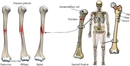
Fig. 1 The different types fracture of the humerusl bone.
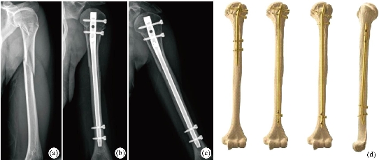
Fig. 2. (a) A 21-year-old woman with segmental fracture at the proximal shaft of the left humerus, which extends to surgical neck. (b) The immediate post-nailing radiograph. (c) The fractures unit anatomical position 1 year after operation. (d) Humerus intramedullary nails system.
Experimental
The biomechanical study was carried out using a calculation program and simulation with finite elements. Using a humerus from a cadaver and the two fixation devices, the geometric parameters and grids were generated, as is explained below.
Creation of Geometric Parameters
Humerus
Actual model of Humerus Bone is obtained by Material’s Interactive Medical Image Control System (MIMICS) software using computed tomography (CT) scanning images. MIMICS has different parts to edit CT images. Reverse engineering software is important here to make necessary improvements. For detailed information about scanning with MIMICS you can see [25]. After obtaining 3D model by using MIMICS software, it is imported to Solidworks format extension (igs, x_t). Solidworks data is imported to ANSYS workbenche16.2 software for the FEA. Modelling the humerus bone for analysis is very difficult because of the complex shape of the bone. Unlike the studies available in the literature bone is an actual humerus bone of a person in this study. Dimensions of the humerus bone are closed to the dimensions of the bone in [26]. The geometric parameters of the tri-dimensional humerus were obtained by means of projections taken from X-rays and CAT scans of a humerus from a cadaver. Series of 3 mm sections of a longitudinal (OZ axis) CAT scan of the humerus made it possible to view cortical and cancellous bone in each section. Subsequently all the CT were scanned to digitalize the hard copy of the humerus. A digital format made it possible to work with a CAD program Corel Trace-Corel Draw v10® (Microsoft, Washington, USA) that extracted the curves of the cortical and cancellous parts of the humerus. Finally the design program Solidworks2017® imported these curves to the corresponding planes, closing the resultant solid volume, that is to say a tri-dimensional humerus (Fig. 4), and from that moment on, a grid could be made.
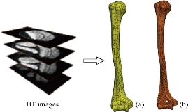
Fig. 3 3D model of humerus bone: (a) cortical bone, and (b) spongy bone.
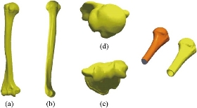
Fig. 4. Final tri-dimensional view of the humerus and thickness of the cortical bone of the diaphysis. Performed with Solidworks2017®. (a) Front view; (b) lateral (left) view; (c) top view; and (d) bottom view.
Fixations
The geometric parameters were obtained with the program Solidworks2017® in the same way as with the humerus from real physical models of fixation. The endomedullary nail used as a model was a UHN® (Synthes, Paoli, SA) of 8 mm in diameter an 180 mm in length, with proximal and distal locking see Fig. 5. Both fixation devices were made of titanium and were contributed by Synthes® (Paoli, USA). The screws were computer designed during pre-processing with finite elements.
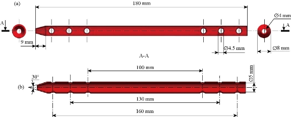
Fig. 5 Nail definition drawing. Performed with Solidworks2017®: (a) front view, and (b) coup section.
Finite element models and implants
Material properties
The finite element analysis was performed in ANSYS Workbench 16.2 (3DS). Linear elastic isotropic material properties were assigned to all models and implant materials. The cortical bone and cancellous bone were assumed with Poisson’s ratio of 0.3 and elastic modulus of 13,800 and 1380 MPa, respectively [27, 29]. The contact behavior of the nail/locking screw and locking screw/bone interfaces was defined as fully fixed. All of the contact elements were defined as deformable elements. The material simulated in the fasteners (nail) and the four screws was titanium alloy Ti-6Al-4Va were assumed with Poisson’s ratio of 0.33 and elastic modulus of 110,000 MPa, respectively [27, 29].
Biomaterials
The materials that are used as biomaterials include polymers, metals, ceramics and composites. The metals used as biomaterials include titanium alloys, cobalt-chromium alloys, and stainless steels. In polymers, ultra high molecular weight polyethylene (UHMWPE) is most commonly used biomaterial. More recently ceramics demonstrated great promise for replacing metals in the nailing system of humerus replacement with the chief benefits of ceramics is their superior wear properties. In this study biomechanical analysis of titanium alloys have been carried out using FEM and compare the results.
Boundary conditions and external loads
The modal analysis is performed for the humerus bone to find natural frequencies in ANSYS software. It’s difficult to give actual boundary conditions from actual places of the bone because of the complex structure of the human body. Three different boundary conditions were used for the modal analysis in the literature to compare Fig. 5. The purpose of this article is to prepare a 3D CAD model of the nailing system from the available literature and to study the von Mises stress distribution and total displacement in the various components of the nailing system including the cortical bone, spongy bone, intermedial nail, and screws. 3D modeling software Solidworks 2016 was used for 3D modeling of the nailing system and finite element analysis. Software ANSYS 16.2 was used for numerical estimation of von Mises stresses and strains. The purpose of this analysis is to reduce the stress on the bone level of the cortical and cancellous bone, using two nailing models for the installation, the first hollow stem model fixed by four parallel screws and the second hollow stem model fixed by six screws parallel to Fig. 5. To evaluate the force conditions, we determined the von Mises stress distribution and the maximum stress on the implants, the cortical bone, and the cancellous bone. The distal segment of the humeral shaft was fixed (Fig. 6). Axial force, shear force, and torsion were applied to the models (Fig. 6). For axial force, 500-N loads oriented vertically in the coronal and sagittal planes were distributed onto the proximal humeral head. On the basis of axial conditions, the angle of the model was changed by 20° to simulate shear force. The shear force simulated the force that a proximal fracture site would experience while the patient was rising out of a chair or crutch weight-bearing. To simulate rotation, a 10-Nm torque was applied to the proximal humeral head around the axis of the humeral shaft. The whole experiment was repeated five times.
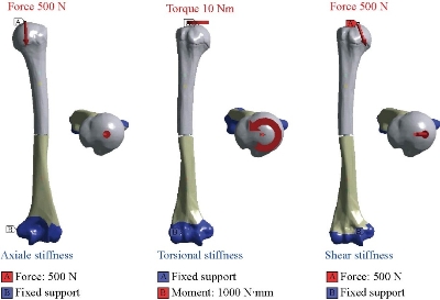
Fig. 6 The distal segment of the humeral shaft was fixed. Axial force, shear force, and torsion were applied to the models.
Element type and meshing
Sano et al. [30] suggested using a SOLID187 element type that could be used to develop the discretization of the humerus model. This element type was composed of 10-node quadratic tetrahedral elements with three degrees of freedom [31]. The humerus model meshed with rigid elements, and limited the size of the model and the evaluation time. Using a small element size and slow size transitions could provide better accuracy [32, 33]. The meshing of the components is simple and consists of 10-node tetrahedral linear elements (Fig. 7). The complete model of humerus (intact model) (Fig. 7) consists of 190,061elements and 303044 nodes (528,651 degrees of freedom). The cortical bone have been modelled with tetrahedral elements (721,33 elements, 129,755 nodes) and the cancellous bone have been modelled with tetrahedral elements (117,928 elements 173,289 nodes) this mentioned in the Fig .7. On the other hand, the humerus with nailing system (IMRS with 4 screws) consisted of 268,255 elements and 472,882 nods (Fig. 8). The humerus with nailing system (IMRS with 6 screws) consisted of 268,255 elements and 472,882 nods, as mentioned in Fig. 9. The interfaces between the different components of the intact model and nailing system (IMRS with 4 screws and 6 screws) were treated as perfectly glued interfaces (Fig. 10).
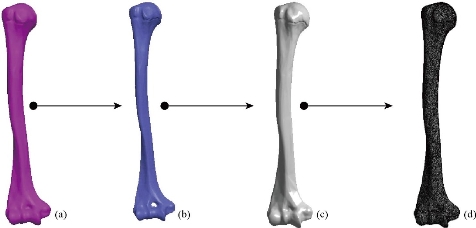
Fig. 7 Steps in 3D bone reconstruction: (a) real bone (cortical bone), (b) spongy bone, (c) 3D model in ANSYS Workbench, and (d) mesh of the humerus model.
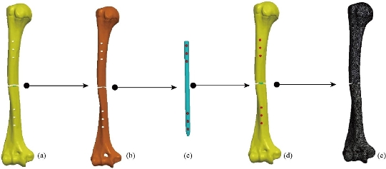
Fig. 8 Steps in 3D bone reconstruction: (a) real bone (cortical bone), (b) spongy bone, (c) nailing system with four screw, (d) assembly drawing of the humerus, and (e) condensed meshing of the humerus (IMRS with 4 screws).
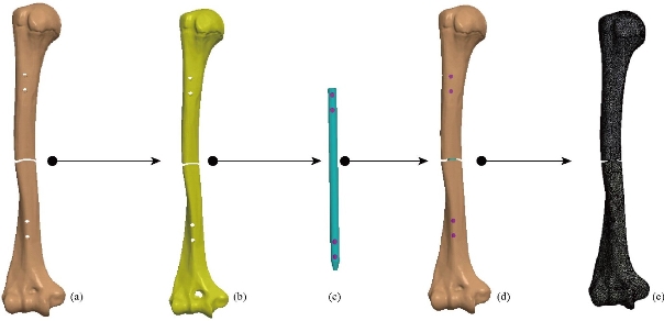
Fig. 9 Steps in 3D bone reconstruction: (a) real bone (cortical bone), (b) spongy bone, (c) nailing system with four screw, (d) assembly drawing of the humerus, and (e) condensed meshing of the humerus (IMRS with 6 screws).
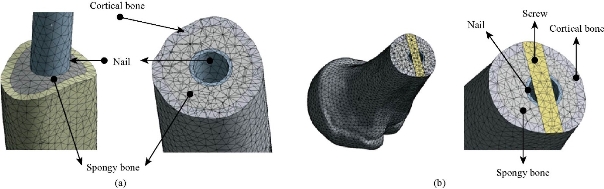
Fig. 10 (a) Mesh confounded between the components of a humerus bone. (b) 3D finite element modeling component of the humerus bone.
Results and Discussion
Maximal von Mises stress and strain in the cortical and spongy bone of the humerus for axial load
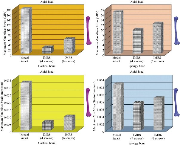
Fig. 11 Histogram of maximum von Mises stresses and strains in the cortical and spongy bone of humerus. The nailing systems IMRS with 4 screws and IMRS with 6 screws reduced the von Mises stresses and strains in axial load. However, the nailing system IMRS with 4 screws reduced the von Mises stresses and strains at the humerus bone in axial load.
Contour of the maximum von Mises stresses and strains in the cortical and cancellous bone of the humerus for axial load
On the other hand, Fig. 12 shows that the maximum von Mises stresses and strains in the spongy bone were equal to 16.501, 9.4585 and 11.856 MPa, and 0.0124, 0.0074 and 0.0087 mm/mm, respectively to the other components of the nailing system. Fig. 10 shows that the implantation of the intramedullary rod (IMRS with 4 screws, IMRS with 6 screws) fixed with screws inserted between the bone superior and inferior of humerus and simulated by the finite element method confirms a decreased of the equivalent stresses in the spongy bone of humerus. We see in Fig. 12 that the levels of von Mises stress and strain in the cortical and spongy bones of the humerus were reduced by supplying the intact model that is to say nailing systems IMRS with 4 screws and IMRS with 6 screws played a role very important in the absorption of stresses and their minimization.
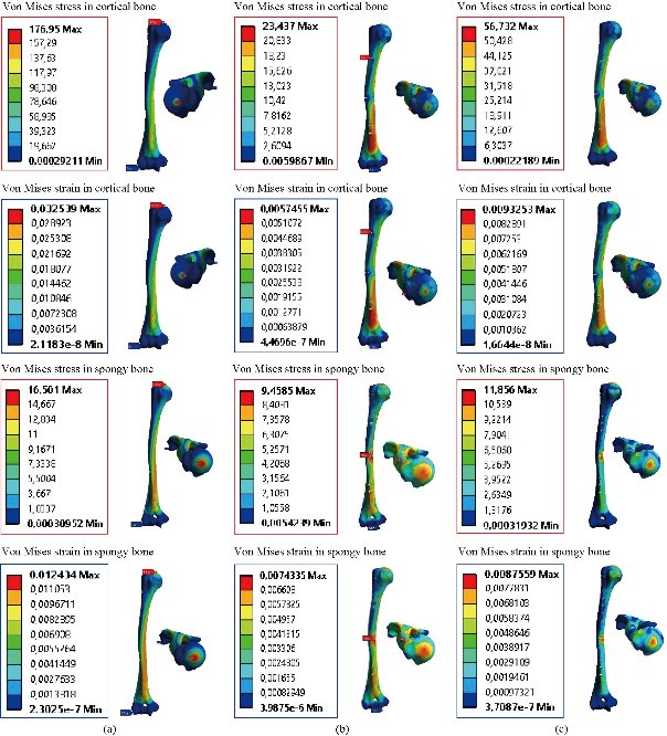
Fig. 12 Distributions of maximum von Mises stresses and strains in the cortical and spongy bone of humerus for axial load: (a) intact model, (b) IMRS with 4 screws, and (c) IMRS with 6 screws.
Contour of the total displacement in the humerus along the x-axis
Fig. 13 presents these contours for three models of humerus (intact model, IMRS with 4 screws, IMRS with 6 screws). In axial loading, axial rotation and inclined force applied to the proximal head of the humerus; the maximum displacement total was revealed in the intact model in the amount of 2.64 mm, 16.24 mm and 1.33 mm for the upper edge of the proximal head of the humerus due to the load. The three loads (axial force, axial and inclined rotational force) applied on the proximal head of the humerus bone caused maximum displacements concentrated on the convex head of the humerus which was equal to 2,2953 mm/mm, 13.237 mm/mm and 0.6868 mm/mm, as mentioned in Fig. 13. We found in Fig.13 that in axial load, the displacement of the structure (IMRS with 4 screws) along the x-axis equaled 2.9553 mm and in axial load the displacement equaled 13.237 mm. In other words, the displacement of the humerus structure along the x-axis under the effect of an inclined equaled to 0.6868 mm. We noted in Fig.13 that the two charges applied to the convex surface of the humerus structure presented a larger displacement equal to 2.7455 mm and 15.183 mm. On the other hand, the inclined force applied to the humerus IMRS with 6 screws structure indicated a displacement contour equal to 0.8755 mm compared with that of an intact model, as mentioned in Fig. 13. We concluded in this figure that the nailing system fixed by four screws indicated a minimum displacement along the x-axis, that is to say, the intramedullary rod played a very important role of stress absorption and minimization.
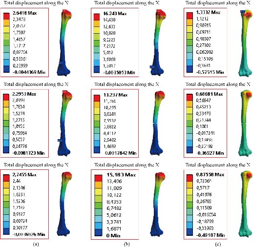
Fig. 13 contour of total displacement along the x-axis for different physiology: (a) Axial force, (b) shear force, and (c) torsion force.
Maximal von Mises stress and strain in the cortical and spongy bones of the humerus for shear load
Fig. 14 shows that the inclined force was applied on the upper surface of the proximal head of the humerus. A contour of the maximum stresses and strains was present as bright red in the cortical bone. We see in this figure that the stress was concentrated to the left side regions and right of the cortical bone of the humerus Fig. 15. For a vertical loading P was inclined at 20 ° with respect to the y-axis applied to the proximal head of the humerus, the implantation of the fracture of the humerus with a static fixation system (nailing) inserted between the two bones fractured and simulated by the finite element method confirmed an increase in von Mises stresses and maximum strains in cancellous bone as equal to 14.779, 31.197 and 42.799 MPa, and 0.0111, 0, 0234, and 0.0310 mm/mm (Fig.15).
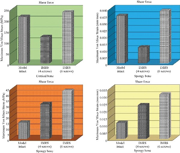
Fig. 14 Histogram of maximum von Mises stresses and strains in the cortical and spongy bones of humerus. The nailing system IMRS with 4 screws reduced the von Mises stresses and strains in the cortical bone under the influence of shear force. However, the nailing systems IMRS with 4 screws and IMRS with 6 screws increased the von Mises stresses and strains at the spongy bone of humerus in shear force.
Contour of the maximum von Mises stress and strain in the cortical and spongy bones of the humerus for shear load
For inclined force applied to the three finite element models, we noted in both Fig. 14 and 15 that the implantation of the IMRS with 4 screws nailing system indicated that the von Mises stresses in the cortical bone decreased to 122,35 MPa by providing the intact model, which justifies that the static fixing system plays a very important role in the stabilization of the movement and the absorption of constraints and their minimization.
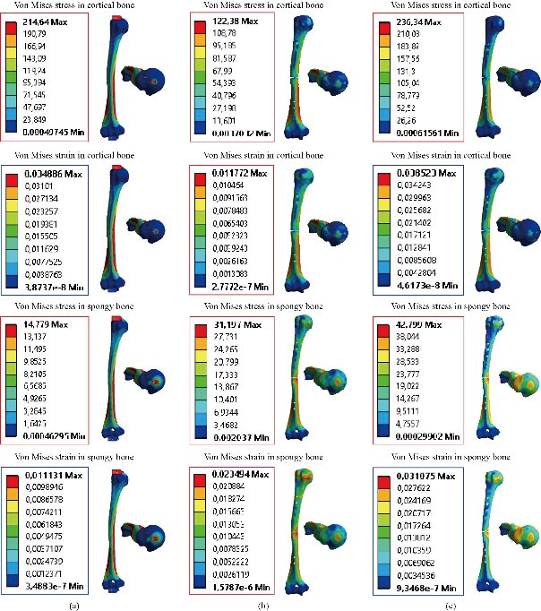
Fig. 15 Distributions of maximum von Mises stresses and strains in the cortical and spongy bones of humerus for shear force: (a) Intact model, (b) IMRS with 4 screws, and (c) IMRS with 6 screws.
Maximal von Mises stress and strain in the cortical and spongy bones of the humerus for axial rotation
Fig. 16 shows that the static fixation system, intramedullary rod with screws, was inserted into the model of the humerus sheared in the middle. The instrumented model was subjected to an axial rotation load P along the y-axis.
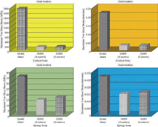
Fig. 16 Histogram of maximum von Mises stresses and strains in the cortical and spongy bones of humerus. The nailing systems IMRS with 4 screws and IMRS with 6 screws reduced the von Mises stresses and strains in axial load. However, the nailing system IMRS with 4 screws reduced the von Mises stresses and strains at the humerus bone in axial load.
Contour of the maximum stresses and strains of von Mises in the cortical and cancellous bone of the humerus for axial rotation
The results showed that the maximum von Mises stresses in cortical and spongy bones were equal to 1742.8, 139.96 and 140.64 MPa, and 35.091, 14.095 and 16.418 MPa, outlined in red in Fig. 17. We conclude that the implantation of the hollow stem into the humerus has reduced von Mises stress on the cortical and cancellous bones in axial rotation, that is, the nailing system with fixation screws can ensure the stability of the movements in axial rotation and can reduce the annular stress of the surgical segment. Fig.16 shows the effect of an axial torque of 10 Nm on the upper surface of the proximal head of the humerus which would generate minimal von Mises strains in both models of IMRS with 4 screws and IMRS with 6 screws, respectively equal to 0.01464 and 0.01575 mm/mm (Fig.16).
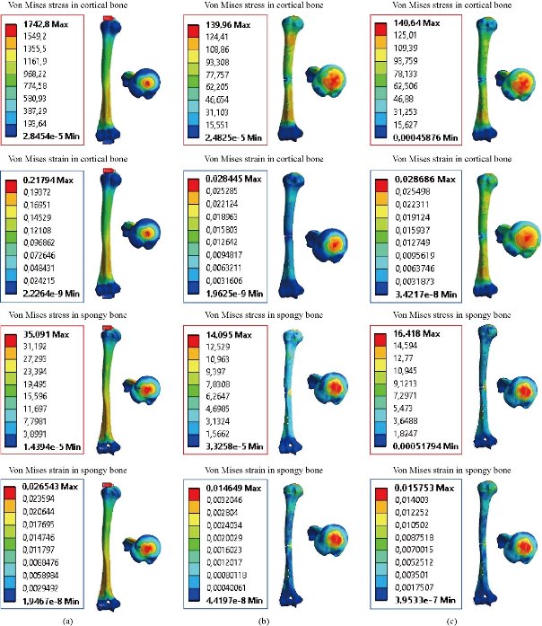
Fig. 17 Distributions of maximum von Mises stresses and strains in the cortical and spongy bones of humerus for torsion force: (a) Intact model, (b) IMRS with 4 screws, abd (c) IMRS with 6 screws.
Contour of the maximum von Mises stresses in the nailing system Model I and Model II
In the first part, the results of the simulation of a compressive load applied to the upper surface of the humerus head were presented, as shown in Fig. 18, where we focused solely on the results of von Mises stress. The von Mises stress histogram in the two nailing systems of IMRS with 4 screws and IMRS with 6 screws is presented as a function of the different physiologies in Fig. 19. In the IMRS with 4 screws nailing system (Ti6Al4V), the equivalent stresses in the intermediate nail with the four nails ranged between 574.92 MPa ≥ σe (Mises) ≥ 0.5692 MPa, and comparing our von Mises stress with the stress of compression of the titanium alloy (Ti6Al4V), σe (nailing system) (Mises) < σcompression (Ti6Al4V) = 970 MPa (Engineering Technique), the resistance condition was verified. On the other hand, regarding the IMRS with 6 screws nailing system (Ti6Al4V), the equivalent stresses in the intermediale nail with the four nails ranged between 206.95 MPa ≥ σe (Mises) ≥ 0.4550 MPa, and comparing our von Mises stress with the compression stress of the titanium alloy (Ti6Al4V), σe (nailing system) (Mises) < σcompression (Ti6Al4V) = 970 MPa (engineering technique), the resistance condition was verified. Fig. 19 indicates the effect of an inclined loading of 500 N applied on the upper surface of the humerus which would generate maximum von Mises stresses at the level of the nailing rod, respectively equal to 1521.8 and 1451.9 MPa (outlined in red see Fig. 18). Furthermore, regarding the two nailing systems IMRS with 4 screws and IMRS with 6 screws manufactured by Ti6Al4V, the equivalent stresses in the rod which was fixed by four screws ranged between 1521.8 MPa ≥ σe (Mises) ≥ 0.94419 MPa and in the rod which was fixed by six screws ranged between 1451.9MPa ≥ σe (Mises) ≥ 1.1618 MPa, by comparing our von Mises stress with the shear strength and compressive stress of titanium alloy (Ti6Al4V), σe (nailing system) (Mises) > σshear (Ti6Al4V) = 550 MPa and σe (nailing system) (Mises) > σcompression (Ti6Al4V) = 970 MPa (engineering technique), the resistance condition was verified. We found in Fig. 18 that a torsion loading of 10 Nm applied on the upper surface of the humerus which would generate maximum von Mises stresses at the level of the nailing rod, respectively equal to 828.82 and 301.83 MPa (outlined in red see Fig. 18). In contrast, the two nailing systems IMRS with 4 screws and IMRS with 6 screws manufactured in Ti6Al4V, the equivalent stresses in the rod which was fixed by four screws ranged between 828.82 MPa ≥ σe (Mises) ≥ 0.77071 MPa and in the rod which is fixed by six screws ranged between 301.83MPa ≥ σe (Mises) ≥ 0.53473 MPa, by comparing our von Mises stress with the shear strength of titanium alloy (Ti6Al4V), σe (IMRS with 4 screws of nailing system) (Mises) > σshear (Ti6Al4V) = 550 MPa and σe (IMRS with 6 screws of nailing system) (Mises) < σshear (Ti6Al4V) = 550 MPa (engineering technique), the condition of resistance was verified.
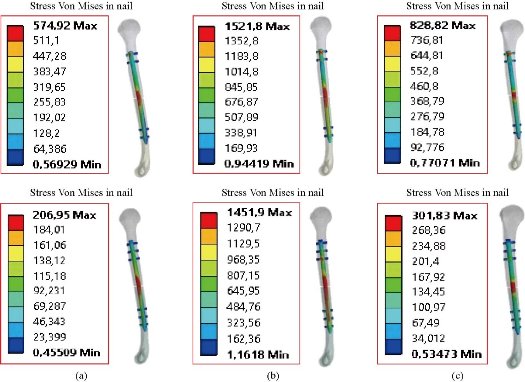
Fig. 18 Distributions of maximum von Mises stresses in the nail for different physiology: (a) Axial force, (b) shear force, and (c) torsion force.
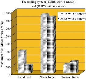
Fig. 19 Histogram of maximum von Mises stresses and strains in the cortical and spongy bones of humerus. The nailing systems IMRS with 4 screws and IMRS with 6 screws reduced the von Mises stresses and strains in axial load. However, the nailing system IMRS with 4 screws reduced the von Mises stresses and strains at the humerus bone in axial load.
Discussion
The information presented in this non-systematic literature review supports the application of the FEA as a useful tool to understand and predict biomechanical incidents. The humerus, shoulder and other joints, such as the hip, the knee and the spine, have been analyzed widely using this method. Nevertheless, the considerations used to apply FEM in some studies presented discrepancies that should not be ignored. The FE modeling of the medial humeral fracture depends particularly on the fracture type that is to be studied. Fig. 11 shows a histogram of maximum von Mises stresses and strains in the cortical and spongy bones of humerus. The nailing systems IMRS with 4 screws and IMRS with 6 screws reduced the von Mises stresses and strains in axial load. In axial load, the intramedullary rod fixed with screws reduced von Mises stress and strain at the cortical bone of humerus, which justifies that the system nailing plays a very important role in stabilizing the movement of the humerus. On the other hand, Fig. 15 shows the distributions of maximum von Mises stresses and strains in the cortical and spongy bones of humerus. The nailing system IMRS with 4 screws reduced the von Mises stresses and strains in the cortical bone under the influence of shear force. However, the nailing systems IMRS with 4 screws and IMRS with 6 screws increased the von Mises stresses and strains at the spongy bone of humerus in shear force. The results in Fig. 17 show that the maximum von Mises stresses in cortical and spongy bones equaled to 1742.8, 139.96 and 140.64 MPa, and 35.091, 14.095 and 16.418 MPa, outlined in red. We conclude that the implantation of the hollow stem into the humerus has reduced von Mises stress on the cortical and cancellous bones in axial rotation, that is, the nailing system with fixation screws can ensure the stability of the movements in axial rotation and can reduce the annular stress of the surgical segment. Fig.16 shows the effect of an axial torque of 10 Nm on the upper surface of the proximal head of the humerus which will generate minimal strains of von Mises in both models (IMRS with 4 screws and IMRS with 4 screws), respectively equal to 0.01464 and 0.01575 mm/mm (Fig. 16). In general, the new model nailing system secured with screws gave a lower level of von Mises stress and strain at the cortical and cancellous bones of the humerus as compared to the intact model.
Conclusions
FEA is an important tool that can be used to understand and predict biomechanical events. However, the accuracy of FEM depends on the details of the model used. With its application in engineering, this method can solve many equations to calculate the stresses based on the mechanical properties of the structures being analyzed. FEM has many advantages highlighted by the possibility of including the heterogeneity and irregularity of the humerus contour in the design of the model and the relative ease with which the charges can be applied to different directions and sizes for further analysis complete. As a general conclusion, on the basis of the results of analysis by this numerical method, the numerical results show that nailing systems IMRS with 4 screws and IMRS with 6 screws have played a very important role in the absorption and minimization of stresses, On the other hand, the nailing system fixed with screws is too great a role in reducing the stress compared to intact model. In general, the new nailing system model secured with screws gave a lower level of von Mises stress and strain at the cortical and cancellous bones of the humerus compared to the intact model.
Acknowledgements
The authors kindly appreciate Mr. Brahim Keddar and Benaoumer Aour for their help in model preparation. All authors had equal role in design, work, statistical analysis and manuscript writing. And this paper has been completed by personal expenses.
Conflict of Interests
The authors declare that no competing interest exists.
References
Copyright© Brahim Keddar, Benaoumer Aour, Samir Zahaf, Chetti Boualem, Fouzia Bouchakour, and Zahra Najafi Vafa. This is an open-access article distributed under the terms of the Creative Commons Attribution License, which permits unrestricted use, distribution, and reproduction in any medium, provided the original author and source are credited.

|
Nano Biomedicine and Engineering. Copyright © Shanghai Jiao Tong University Press |
 |