Research Article
Numerical Study of the Effect of Elastomer and Cement of Stress Absorbers on the Reduction of Stresses in Tibia and Tibial Bone Analysed by Finite Element Method
Abdelkader Mestar 1*, Samir Zahaf 2*, Nourddine Zina 3, Ahmed Boutaous 1
1 Département technologie des matériaux, université des sciences et de la technologie d’Oran Mohamed Boudiaf, USTO-MB, BP 1505, EL M’naouer, 31000 Oran Algérie.
2 Département de génie mécanique, université des sciences et de la technologie d’Oran Mohamed Boudiaf, USTO-MB, BP 1505, EL M’naouer, 31000 Oran Algérie.
3 Département de génie mécanique, Ecole nationale polytechnique d’Oran BP 1523 M’naour, Oran 31000 Algeria.
* Corresponding authors. E-mail: abdelkader.mestar@univ-usto.dz or mestarkader@yahoo.fr; samir.zehaf@univ-usto.dz or zahafsamir1983@gmail.com; Tel.:+213-65954803
Received: Feb. 16, 2018; Accepted: Mar. 27, 2018; Published: Mar. 29, 2018
Citation: Abdelkader Mestar, Samir Zahaf, Nourddine Zina, and Ahmed Boutaous, Numerical Study of the Effect of Elastomer and Cement of Stress Absorbers on the Reduction of Stresses in Tibia and Tibial Bone Analysed by Finite Element Method. Nano Biomed. Eng., 2018, 10(1): 56-78.
DOI: 10.5101/nbe.v10i1.p56-78.
Abstract.
Metal alloys have been the materials of choice since the start of orthopaedic surgery. Orthopedic materials must fulfill the mechanical, biological and physical necessities of their proposed utilization. Knee joint is the most complex joint in human body, which gets the discriminating loads in different moving conditions. Accordingly, the material utilized for knee implant is assumed the exceptionally essential part for long survival of knee prosthesis. The materials that are utilized as biomaterials incorporate polymers, metals, ceramics and composites. Out of those materials, cobalt-chromium alloys, titanium alloys, stainless steel and ultra high molecular weight polyethylene are the most usually utilized biomaterials for knee implants. The objective of this paper is to prepare three models of prosthesis knee joint from available literature and study on the distribution of von Mises stresses and strains in different components of knee prosthesis. It is known that the total displacement between the intact model and the artificial model of knee, 3D modeling software Solidworks 2016 is used for 3D modeling of knee prosthesis, and that finite element analysis software ANSYS 16.2 was used for numerical estimation of von Mises stresses and strains. We found in this study that the maximum von Mises stresses and strains at the level of the tibial and tibial bone decreased, that is to say, the cement and the elastomer played a very important role in the absorption of the stresses and their minimization. On the other hand, the four knee prostheses (model I (Ti6Al4V), model II (CoCrMo), model III (316L SS), model IV (ZrO2)) implanted by elastomer contributed significantly to the reduction of stresses in the patella bone compared to the intact model. In general, both models of the knee prosthesis and those reinforced by a stress reduction system (cement or elastomer) gave a lower stress level in the tibia and tibial bone of a normal person compared to a healthy model. The results obtained provide a theoretical basis for choosing an appropriate surgical model.
Keywords: Biomaterials; FEA (finite element analysis); Prosthesis; TKR (total knee replacement); UHMWPE (ultra high molecular weight polyethylene); von Misses stress; Strains; Cobalt-chromium alloys; Titanium alloys; Stainless steel
Introduction
The knee joint, the largest diarthrosis in the human body, is a complex synovial joint with bone ends, cartilage, synovial membrane, ligaments, etc. This articulation can be considered during its movement as a mechanism whose understanding of functioning irremediably leads to tribological questions. From its anatomy (Fig.1), the cartilage can be considered as the first two bodies and the synovial fluid as the third body. The articulated lubrication system allows it to work under different conditions, from high loadings at low speeds to low loads at high speeds. The knee joint has the ability to move from the rest position to the movement, under severe conditions without any damage [1]. The exemplary lubrication, in the contact of the articular surfaces, is reflected by a minimum of energy dissipation and a coefficient of friction varying between 0.005 and 0.25 [2], which is, in general, much less than in the bearings. Wear is minimal under normal circumstances and cartilage surfaces last a life time of 70 years or more. However, the function of the synovial joint may be impaired by diseases such as arthritis or osteoarthritis, by accidents that damage joint surfaces or by abnormal use of the joint. Any biological, chemical or mechanical change in the joint makes it lose its function. His ability to move freely is limited and very often pain appears. A complete replacement of the joint articular can take place to put an end to the pains and to restore its mobility. Joint prostheses must have a low coefficient of friction, low wear, resistance to mechanical failure and loosening. A good understanding of implant performance is very important. The main objective of the article is to develop a three-dimensional (3D) solid biomechanical model consisting of (femur, tibia, tibial, ligament, patella, cartilage, meniscus, knee prosthesis), stress reduction and strain in the tibia bone and tibial. In the context of this objective, we have proposed two total knee prostheses consisting of (femoral implant, tibia implant, polyethylene insert), to reduce the stresses and strains in the tibia and tibial bone, we propose in this section implanted the elastomer between the tibia implant and the polyethylene insert in the four prosthesis of knee ((model I (Ti6Al4V), model II (CoCrMo), model III (316L SS), model IV (ZrO2)) and for model five of the knee prosthesis (model V) attached the lower implant in the tibia bone with the cement, In this section, a thorough study of stress distributions and elastic strains in the components of the knee prosthesis as a function of the supported loads should be made. We then studied the nature of equivalent stresses with different biomaterials with the use of elemental analysis and to find the best biomaterial for the knee prosthesis. Solidworks 2016 has been used for solid modeling of knee implant components. The finite element analysis (FEA) of the knee prosthesis using different biomaterials was performed in the analysis software ANSYS workbenche 16.2 by applying the load in the upper surface of the femur and fixed embedding at the low level of the tibia and tibial bone.
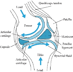
Fig.1 Representation of the knee joint.
Experimental
In this study, three models of knee were constructed : The first model was that of an intact knee joint. The second model consisted of femoral implant, tibia implant, medial implant, polyethylene insert and elastomer, as mentioned in Fig. 2 and 7. The third model consisted of femoral implant, tibia implant, polyethylene insert and cement, as indicated in Fig. 11.
Finite element (FE) model of the intact knee joint (intact model)
Geometries of bony structures and soft tissues were taken from a healthy human knee of a 24-year old man. Solid models of the femur and tibia and geometries of soft tissues including articular cartilages and menisci were obtained from the magnetic resonance images (MRI). Each image was taken at 3.2 mm interval in a sagittal plane. These data were used to create a three dimensional computer aided design (3D CAD) model in order to import into Ansys workbenche 16.2 software for FEA. The knee was composed of a bony structure (distal femur, tibia, tibial and proximal patella), a cartilaginous structure (femur, tibia and patella), menisci (medial and lateral), ligaments (anterior and posterior cruciate, medial and lateral collateral, and medial and lateral patello-femoral), as mentioned in Fig. 3. Anatomy of the model was created from magnetic resonance images, and the biomechanical characteristics used in the model were based on experimental data available in the literature. A previously developed model in the European project “Knee-up” was adapted for use in the current study (Fig. 3) [3, 4]. The femur and tibia were modeled as rigid in first simulation because they have much larger stiffness compared to that of soft tissues. This is time efficient in a non-linear analysis and as confirmed from previous study [5] that this simplification has no considerable effect on contact variables. In the second simulation, the femur was modeled as deformable material under static load of 500N at 0o flexion angle to determine stress distribution on the tibia and tibial bone. The three cortical bone (femur, tibia and patella) were modeled as orthotropic elastic with E1=12 (GPa), E2=13.4 (GPa), E3=20 (GPa), G12=4.53 (GPa), G13=5.61 (GPa), G23=6.23(GPa), υ12=0.38, υ 13=0.22 and υ 23=0.24 [6], where direction 1, 2 and 3 were radial, circumferential and long axis of the bone, respectively. The cartilage was defined as a homogeneous linearly isotropic elastic material with E=15MPa and υ =0.475 [7] and the menisci was modeled as linear elastic isotropic material, as previously described (Table 2) [8]. All five ligaments (lateral collateral ligament (LCL), posterior cruciate ligament, ligament tibial, medial collateral ligament (MCL), and patella ligament) were defined as a homogeneous linearly isotropic elastic material with E=6 MPa and υ =0.33 [9-15]. The EF models of the femur and tibia bones of the subject were created to demonstrate the comparison between the intact knee model and the two artificial models, to know the effect of compession loading on the components of the knee prosthesis, which is the biomaterials that gives less stress in the tibia and tibal bone. The length of the distal femur was 42 mm and the length of the proximal tibia was 44 mm. Geometries of the femur and tibia were generated from a CAD model created using the technique described [16]. The geometries were exported to ANSYS Workbenche 16.2 and were modeled by tetrahedral elements, type (Solid187) using HyperMesh (Altair Inc., Troy, MI) (Fig. 4). The resulting femur model consisted of 479,497 elements and 676604 nods. The tibia and tibial FE models consisted of 447218 elements, 62440 elements and 625854 nods, 94168 nods, the patella consisted of 25094 elements and 36292 nods. The cartilages femur and tibia consisted of 57755 elements and 92406 nods, the system ligaments consisted of 41120 elements and 68096 nods, the menisci consisted of 10476 elements and 17312 nods.
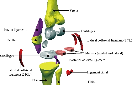
Fig. 2 Different parts in 3D model of human knee.
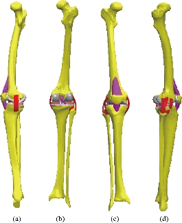
Fig. 3 Knee model studied: (a) Lateral (left) view; (b) Dorsal view; (c) Front view; and (d) Lateral (right) view.
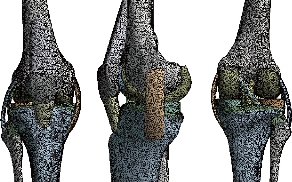
Fig. 4 FE model of the intact knee (intact model).
Biomaterials
The materials that are used as biomaterials include polymers, metals, ceramics and composites. The metals used as biomaterials include titanium alloys, cobalt-chromium alloys, and stainless steels. In polymers UHMWPE (ultra high molecular weight polyethylene) is most commonly used biomaterial. More recently, ceramics demonstrated great promise for replacing metals in total knee replacement with the chief benefits of ceramics are their superior wear properties. In this study, biomechanical analysis of titanium alloys, cobalt-chromium alloys, stainless steels and UHMWPE have been carried out using FEM and compare the results. Materials used for manufacturing the femoral component of implant are Ti6Al4V alloy, Co-Cr-Mo alloy, SS 316L alloy and oxidized zirconium and the commonly used material for manufacturing the linear insert now a days is UHMWPE (ultra high molecular weight polyethylene). The material properties that were being used for the analysis are mentioned in Table 1.
Table 1 Properties of different biocompatible materials widely used for prosthesis [17-20]
|
Material |
Density (kg/m3) |
(MPa) |
Poisson's ratio υ |
Yield strength (MPa) |
Ultimate strength (MPa) |
Re (MPa) |
|
Fibula |
1.91 |
- |
- |
- |
100 |
- |
|
Tibia |
1.96 |
- |
- |
- |
156.71 |
- |
|
Femur |
1.91 |
- |
- |
- |
141 |
- |
|
UHMWPE |
930 |
690 |
0.29 |
21 |
48 |
30 |
|
Ti6Al4V |
4430 |
115000 |
0.342 |
880 |
950 |
1 200 |
|
CoCrMo |
8300 |
230000 |
0.3 |
612 |
970 |
700 to 1450 |
|
316L SS |
8000 |
197000 |
0.3 |
280 |
635 |
590-1350 |
|
ZrO2 |
6040 |
210000 |
0.3 |
908 |
2000 |
1800 |
Note : Re = Elastic limit or elastic resistance
Table 2 The properties of the materials used for the model of knee joint
|
Components |
Elastic module (E) (MPa) |
Poisson's ratio : υ |
References |
|
|
Cartilage |
15 |
0.475 |
[17-20] |
|
|
Meniscus |
27.5 |
0.33 |
[17-20] |
|
|
ligaments |
6 |
0.33 |
[17-20] |
|
|
Cortical bone |
E1=12000, E2=13400 E3=20000 |
G12=4530 G13=5610 G23=6230 |
V12=0.38 V13=0.22 V23=0.24 |
[17-20] |
|
UHMWPE |
690 |
0.29 |
[17-20] |
|
|
Polyethylene (PE) |
2200 |
0.3 |
[17-20] |
|
|
Ti6Al4V |
115000 |
0.342 |
[17-20] |
|
|
CoCrMo |
230000 |
0.3 |
[17-20] |
|
|
316L SS |
197000 |
0.3 |
[17-20] |
|
|
ZrO2 |
210000 |
0.3 |
[17-20] |
|
|
Elastomer |
0 ,6 |
0.49 |
[17-20] |
|
|
Cement |
2300 |
0,25 |
[17-20] |
|
FE model of the knee prosthesis (model I)
The existing geometrical model of the implant realized with CAO software (Solidworks 2016) was imported. It consists of an assembly of five parts: femoral component, polyethylene insert, implant medium, tibia component and elastomer. In this study we scraped the two cartilages and replaced by two implants (femur and tibia), the fixation of the two components femoral implant and tibia is done by pressure or by force see Fig. 5 and 7. The interfaces between the different components of the knee prosthesis system, namely, femur bone, tibia bone, ligament, polyethylene insert, femur implant, tibia implant and medial implant were treated as perfectly glued interfaces. The geometry of these contact surfaces has therefore been simplified on the geometric model (Fig. 7) in order to facilitate the meshing and calculation steps. The metal parts (Femoral Component, the Implant medium, Tibia component) were modelled with four biomaterials (Ti6Al4V, CoCr MO, 316L SS, ZrO2) with elastic properties, Young’s modulus and Poisson’s ratio were mentioned in Table 1, respectively. The deformable parts (polyethylene insert and elastomer) were behaviour with an elastic behaviour of a silicone; Young’s modulus and Poisson’s ratio were indicated in the Table 2. The knee prosthesis (model I) consisted of 268,255 elements and 472,882 nods (Fig. 6).
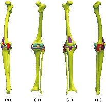
Fig. 5 Knee model studied: (a) Lateral (left) view; (b) Dorsal view; (c) Front view; and (d) Lateral (right) view.
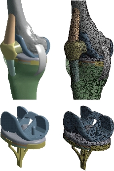
Fig. 6 FE model of the knee prosthesis (model I).
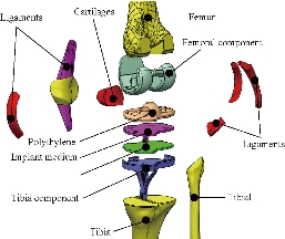
Fig. 7 Different parts in 3D model of human knee prothesis (model I).
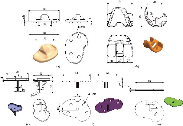
Fig. 8 Definition drawing of the various components of the knee prosthesis (model I): (a) Insert polyethylene; (b) Femoral component; (c) Tibia component; (d) Implant medial ; and (e) Cement.
FE model of the knee prosthesis (model V)
The existing geometrical model of the implant realized with CAO software (Solidworks 2016) was imported. It consists of an assembly of four parts: Femoral Component, polyethylene insert, Tibia component and cement. In this study, we scraped the two cartilages and replaced them by two implants (femur and tibia). Femoral implant fixation was done by pressure or by force; fixation of the tibia implant in the bone was done by a bonding system (cement) (Fig. 11). The interfaces between the different components of the knee prosthesis system, namely, femur bone, tibia bone, ligament, polyethylene insert, femur implant, tibia implant and medial implant were treated as perfectly glued interfaces. The geometry of these contact surfaces was therefore simplified on the geometric model (Fig. 9) in order to facilitate the meshing and calculation steps. The metal parts (femoral component, tibia component) were modelled with four biomaterials (Ti6Al4V, CoCr MO, 316L SS and ZrO2) with elastic properties. Young’s modulus and Poisson’s ratio were mentioned in Table 1, respectively. The deformable part (polyethylene insert) was behaviour with an elastic behaviour of a silicone. Young’s modulus and Poisson’s ratio were indicated in Table 2. The knee prosthesis (model V) consisted of 116,1540 elements and 167,5353 nods (Fig. 10).
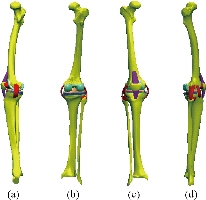
Fig. 9 Knee model studied: (a) Lateral (left) view; (b) Dorsal view; (c) Front view; (d) Lateral (right) view.
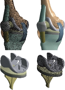
Fig. 10 FE model of the knee prosthesis (model V).
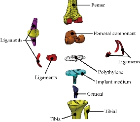
Fig. 11 Different parts in 3D model of human knee prothesis (model V).
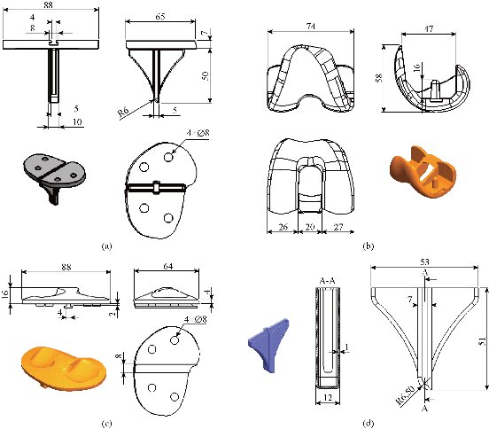
Fig. 12 Definition drawing of the various components of the knee prosthesis (model V): (a) Tibia component; (b) Femoral component; (c) Polyethylene core; and (d) Cement.
Load and boundary conditions
The tibial tray and femoral component in these models were fully bonded to the femur and tibia bone respectively, simulating the use of cement and elastomer [28]. The PE mobile‑bearing was free to translate and rotate with respect to the surface of the tibial tray [29-28]. A compressive axis load of 500 N, consistent with the load magnitude in previous studies, was applied to the upper surface of the femur in the model validation step [22-29]. The femur was constrained only in flexion‑extension while the tibia and fibula were completely fixed at their distal ends, see the Fig.13 [29]. Loads 500 N along Y negative direction were applied on the mechanical axis of top femur in order to simulate the weight of human upper body in this model. In all the analyses, tibia and fibula were kept fixed, as indicated in Fig. 13. The flexion angle θ was defined as the angle from standing position to the flexion state at this time in plane oyz (Fig.13). This finite element model was solved and analyzed with the FE software Ansys workbenche 16.2. The tibial tray and femoral component in model V were fully bonded to the femur and tibia bone respectively, simulating the use of cement [21].
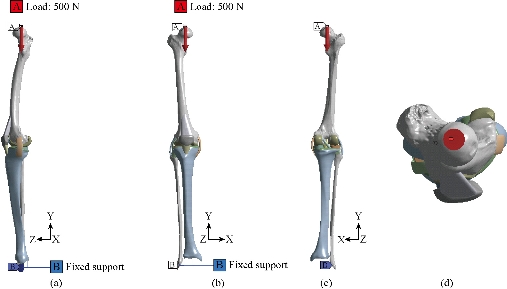
Fig. 13 Biomechanical model of the knee prosthesis: (a) Lateral (left) view; (b) Front view; (c) Dorsal view; and (d) Top view
Results and Discussion
In the first part, the results of the simulation of a load applied to the upper surface of the femur cup have been presented, as mentioned in Fig. 14, where we concentrated only on the results of von Mises stress and strain. The histogram of stresses and strains in the femurs given in Fig. 14 shows that for the eccentric loading on the upper surface of the cup, the equivalent stresses were concentrated in the four femur bone (model I, model II, model III and model IV) which were respectively equal to 363.06 MPa. Fig. 15 shows that the loading of a vertical force of 500 N showed a maximum von Mises strains in the two femurs bones (intact model and model V (cement)) by providing the other system components of the knee prosthesis. Fig. 14 shows the effect of a compression loading of 50 kg on the upper surface of the femur which will generate maximum von Mises strains respectively equal to 0.042556 mm / mm (Fig.15). On the other hand, the eccentric loading (load away from the longitudinal axis of the femur) generated a left lateral bending moment. Hence, the four femurs bone for the four total knee prostheses (model I, model II, model III and model IV) supported a minimum von Mises strain equal to 0.0038549 mm / mm, compared to other components of the system of the knee prosthesis (Fig.15). Fig.16 shows a histogram of von Mises stresses and strains in the tibia bone, indicating that the von Mises stresses in the tibia bone were maximal in the following four models: model I (Ti6Al4V), model II (CoCrMo), model III (316L SS) and model IV (ZrO2). We found in this figure that von Mises strains in the tibia bone were maximal in the intact model and model V with cement. A loading applied on the upper surface of the femur caused to a high concentration of maximum normal stresses in the tibia bone (the red part in Fig. 17). The four knee prostheses with elastomers (model I, model II, model III and model IV) supportrd a maximum von Mises stress equal to 11.16 MPa, 11.711 MPa, 10.999 Mpa and 11.198Mpa. On the other hand, the equivalent stresses were minimal at intact model and model V with (cement), as indicated in the anterior and posterior parts (red outline) compared to the other components of the knee prosthesis system. The 3D knee model of a normal person implanted with five different prostheses was subjected to a P1 compression load. The compression loading effect was analyzed by FEM, showing concentrated minimal strains in the anterior and posterior part of the tibia bone (model I, model II, model III and model IV) respectively equal to 6.09E-05 mm/mm, 6.33E-05 mm/mm, 5.95E-05 mm/mm and 6.10E-05 mm/mm (Fig. 17)]. We found that the knee prosthesis with cement supported normal elastic stresses and strains equal to 3.1392 mm/mm and 0.00021 mm / mm, respectively. In addition, cement with a thickness of 3 mm also played a large role in the absorption of stress and their minimization. Fig. 18 shows the effect of a compression load P1 on the upper femur articulation (intact model, model I, model II, model III, model IV and model V) which would generate von Mises stresses respectively equal to 2, 8746 MPa, 2.1836 MPa, 2.2579 MPa, 2.1255 MPa, 2.1985 Mpa and 2.4144 MPa. Note that the tibial bone for the five total knee prostheses (model I, model II, model III, model IV and model V) supported a maximum strains value respectively equal to 1.09E-05 mm/mm, 1.13E. -05 mm/mm, 1.06E-05 mm/mm, 1.10E-05 mm/mm and 1.70E-04 mm/mm, compared to the other components of the knee prosthesis system. On the other hand, this figure shows that the stresses and strains equivalent to the levels of the tibial bone (model I, model II, model III, model IV and model V) were minimal, that is to say the elastomer for each model played a very important role in the absorption of stresses and strains equal to 2.1836 MPa, 2.2579 MPa, 2.125 Mpa and 2.1985 Mpa, 1.09E-05 mm/mm, 1.13E-05 mm/mm, 1.06E-05 mm/mm, and 1.10E-05 mm/mm respectively, compared to the other components of the total knee arthroplasty system. In conclusion, all simulated cases were able to significantly stabilize the indexed segment (reduced range of motion), with substantial biomechanical advantages. Fig. 20 gives the histogram of the maximum stresses and strains in the femoral implants of the knee prostheses (model I, model II, model III, model IV and model V). Lateral compression loading on the upper superior surface of the femur generated von Mises stresses respectively equal to 529.24 MPa, 609.62 MPa, 781.59 MPa, 492.39 Mpa and 38.755MPa. In the first part, we presented the results of the simulation of a P1 compression load applied on five types of knee prosthesis, where we focused only on the results of von Mises stresses and strains. In the first prosthesis (CoCrMo), the equivalent stresses in the upper plate varied between 529.24 MPa ≥ σe (Mise) ≥ 0.0036978 MPa. And comparing our von Mises stress put with the elastic limit of the chromium-cobalt alloy (CoCrMo). σe (prosthesis) (Mises) <Re (CoCrMo)) = 1450 MPa (Engineering Technique), the resistance condition was verified (Fig. 20). In the second prosthesis (Ti6Al4V), the equivalent stresses in the upper plate varied between 609.62MPa ≥ σe (Mises) ≥ 0.002578 MPa. And comparing our von Mises stress put with the elastic limit of the titanium alloy (Ti6Al4V), σe (prosthesis) (Mises) < Re (Ti6Al4V) = 1200 Mpa (Engineering Technique), the resistance condition was verified. In the third prosthesis (316 L SS), the equivalent stresses in the upper plate vary between: [781.59MPa ≥ σe (Mises) ≥ 0.002614 MPa]. And comparing our von Mises stress put with the elastic limit of the stainless steel alloy (316L SS). [σe (prosthesis) (Mises) <Re (316 L SS) = 1350 MPa]. (Engineering Technique) The resistance condition is verified. In the fourth prosthesis (ZrO2) the equivalent stresses in the upper plate varied between 492.39 MPa ≥ σe (Mises) ≥ 0.002030 MPa. And comparing our von stress stress put with the elastic limit of the zircon (ZrO2), σe (prosthesis) (Miss) < Re (ZrO2) = 1800 Mpa (Engineering Technique), the resistance condition was verified (Fig. 21). In the fifth prosthesis (CoCrMo) with cement, the equivalent stresses in the upper plate varied between 38.755 MPa ≥ σe (Mises) ≥ 0.007555 MPa. And comparing our von Mises stress put with the elastic limit of chromium-cobalt alloy (CoCrMo), σe (prosthesis) (set) < Re (CoCrMo) = 1450 MPa (Engineering Technique), the resistance condition was verified (Fig. 20). And finally we noticed that there was a small difference among the five simulated models. According to the resistance results of the four alloy types of the femoral implant knee prostheses (σe (Mises) of the upper implant of the knee prosthesis < Re, the elastic limit of each material evidenced that the four materials played a very important role in minimizing stress and stabilizing movement. The histogram of the maximum von Mises stresses and strains given in Fig. 22 shows that the lower implant for the four knee prostheses (model I, model II, model III and model IV) underwent a concentration of the maximum stresses concentrated in the border zone of the implant (outline in red), i.e. the strains in the tibial cartilage were respectively equal to 0.091843 mm/mm. In the first prosthesis (CoCrMo), the equivalent stresses in the upper implant varied between 22.646 MPa ≥ σe (Mises) ≥ 0.013845 MPa. And comparing our von Mises stress put with the elastic limit of the chromium-cobalt alloy (CoCrMo), σe (prosthesis) (Mises) < Re (TAV6) = 1450 MPa (Engineering Technique), the resistance condition was verified (Fig. 23). In the second prosthesis (Ti6Al4V), the equivalent stresses in the upper plate varied between 24.1 MPa ≥ σe (Mises) ≥ 0.0068764 MPa. And comparing our von Mises stress put with the elastic limit of the titanium alloy (Ti6Al4V), σe (prosthesis) (Mises) < Re (Ti6Al4V) = 1200 MPa (Engineering Technique), the resistance condition was verified. In the third prosthesis (316 L SS), the equivalent stresses in the upper plate varied between 26,116 MPa ≥ σe (Mises) ≥ 0.011519 MPa. And comparing our von Mises stress put with the elastic limit of the stainless steel alloy (316L SS), σe (prosthesis) (Mises) < Re (316 L SS) = 1350 MPa (Engineering Technique), the resistance condition was verified. In the fourth prosthesis (ZrO2), the equivalent stresses in the upper plate varied between 492.39 MPa ≥ σe (Mises) ≥ 0.002030MPa. And comparing our von Mises stress put with the elastic limit of the zircon alloy (ZrO2), σe (prosthesis) (Mises) < Re (ZrO2) = 1450 MPa (Engineering Technique), the resistance condition was verified (Fig. 23). In the fifth prosthesis (CoCrMo) with cement, the equivalent stresses in the upper plate varied between 22.284 MPa ≥ σe (Mises) ≥ 0.012557 MPa. And comparing our von stress put with the elastic limit of the chromium-cobalt alloy (ZrO2), σe (prosthesis) (Mises) < Re (CoCrMo) = 1400 MPa (Engineering Technique), the resistance condition was verified (Fig. 23). And finally we noticed that there was a small difference between the five simulated models. According to the resistance results of the four types of alloys of the tibia implant of the knee prostheses (σe (Mises) of the superior implant of the knee prosthesis < Re, the elastic limit of each materialwas evidence that the four materials played a very important role of minimizing stress and stabilizing movement. Fig.24 shows the effect of a vertical loading of 50 kg on knee prostheses (intact model, model I, model II, model III, model IV and model V) which would generate maximum von Mises stresses and strains concentrated on the two menisci (left plus right) of the intact model respectively equal to 2.1888 MPa and 0.0963E-02 mm/mm (Fig.25). An eccentric loading applied to a finite element knee model results in a high concentration of maximum normal stresses at the polyethylene core femoral joint for each instrumented prosthesis (model I, model II, model III, model IV and model V) (red part). On the other hand, legend strains at the level of the polyethylene core of the prosthesis (model IV) was minimal. In the first prosthesis (CoCrMo), the equivalent stresses in the insert polyethylene varied between 0.58664 MPa ≥ σe (Mises) ≥ 0.00054979 MPa. And comparing our von Mises stress put with the elastic limit of the polyethylene (PE), σe (prosthesis) (Mises) < Re (polyethylene (PE)) = 30 MPa (Engineering Technique), the resistance condition was verified (Fig. 25). In the second prosthesis (Ti6Al4V), the equivalent stresses in the insert polyethylene varied between 0.597 MPa ≥ σe (Mises) ≥ 0.00050794 MPa. And comparing our von Mises stress put with the elastic limit of the polyethylene (PE), σe (prosthesis) (Mises) < Re (polyethylene (PE)) = 30 MPa (Engineering Technique), the resistance condition was verified (Fig. 25). In the third prosthesis (316 L SS), the equivalent stresses in the insert polyethylene varied between 0.59847 MPa ≥ σe (Mises) ≥ 0.00060709 MPa. And comparing our von Mises stress put with the elastic limit of the polyethylene (PE), σe (prosthesis) (Mises) < Re (polyethylene (PE)) = 30 MPa (Engineering Technique), the resistance condition was verified (Fig. 25). In the fourth prosthesis (ZrO2), the equivalent stresses in the polyethylene (PE) varied between 0.58562 MPa ≥ σe (Mises) ≥ 0.00054122 MPa. And comparing our von Mises stress put with the elastic limit of the polyethylene (PE), σe (prosthesis) (Mises) < Re (polyethylene (PE)) = 30 MPa (Engineering Technique), the resistance condition was verified (Fig. 25). In the fifth prosthesis (CoCrMo) with cement the equivalent stresses in the upper plate varied between 1.1249 MPa ≥ σe (Mises) ≥ 0.00072609 MPa. And comparing our von stress put with the elastic limit of the polyethylene (PE), σe (prosthesis) (Mises) < Re (polyethylene (PE)) = 30 MPa (Engineering Technique), the resistance condition was verified (Fig. 25). And finally we noticed that there was a small difference between the five simulated models. According to the resistance results of the four types of alloys of the tibia implant of the knee prostheses (σe (Mises) of the insert polyethylene of the knee prosthesis < Re, the elastic limit of each material evidenced that the four materials played a very important role of minimizing stress and stabilizing movement. In the first prosthesis (CoCrMo), the equivalent stresses in the medial implant varied between 21.876 MPa ≥ σe (Mises) ≥ 0.11915 MPa. And comparing our von stress put with the elastic limit of the chromium-cobalt alloy (CoCrMo), σe (prosthesis) (Mises) < Re (CoCrMo) = 1450 MPa (Engineering Technique), the resistance condition was checked (Fig. 26). In the second prosthesis (Ti6Al4V), the equivalent stresses in the median plateau varied between 22.433 MPa ≥ σe (Mises) ≥ 0.11542 MPa. And comparing our von stress put with the elastic limit of the titanium alloy (Ti6Al4V), σe (prosthesis) (Mises) < Re (Ti6Al4V) = 1200 MPa (Engineering Technique), the resistance condition was checked (Fig. 26). In the third prosthesis (316 L SS), the equivalent stresses in the upper plate varied between 22.064 MPa ≥ σe (Mises) ≥ 0.12579 MPa. And comparing our von stress put with the elastic limit of the stainless steel alloy (316L SS), σe (prosthesis) (Mises) < Re (316 L SS) = 1350 MPa (Engineering Technique), the resistance condition was checked (Fig. 26). In the fourth prosthesis (ZrO2), the equivalent stresses in the upper plate varied between 21.84 MPa ≥ σe (Mises) ≥ 0.002030MPa. And comparing our von stress put with the elastic limit of the zircon alloy (ZrO2), σe (prosthesis) (Mises) < Re (ZrO2) = 1800 MPa (Engineering Technique), the resistance condition was checked (Fig. 26). According to the resistance results of the four types of alloys of the medial implant of the knee prostheses (σe (Mises) of the median implant of the knee prosthesis < Re, the elastic limit of each material was evidence that the four materials played a very important role in minimizing stress and stabilizing movement. Fig. 27 shows the effect of a compression loading P1 on the elastomer and the cement which would generate von Mises stresses respectively equal to 9.21E-03 MPa, 9.33E-03 MPa, 8.76E-03 MPa, 9.25E-03 Mpa and 0.67198 MPa. It was noted that the cement between the inferior tibia implant and the tibia bone supported maximum stresses and strains respectively equal to 0.67198 Mpa and 0.00032186 mm/mm, compared to other components of the system of the knee prosthesis (Fig. 28). The distribution of von Mises stresses in the elastomer showed an increase in the joint connection zone between the upper femoral implant and the lower tibia implant. We also found another concentration of these stresses on the lower cement surface in contact with the tibia bone. In sum, these results showed that the stress level at the interface of the tibia bone in the cemented model was lower than that for the intact model. Based on the principle of importance of the elastomer and the cement in the reduction stresses in the bone part, especially when we know that the latter was the most important part in this study given the relative stresses, we know that the latter was mainly due to the loads applied to the implant. The knee model of a normal person implanted with five total knee prostheses was subjected to a P1 compression load. The effect of the compression loading was analyzed by FEM, showing concentrated maximum stresses in the bone patella respectively equal to 0.13515 MPa, 2.59E-02 MPa, 2.58E-02 MPa, 2.02E-022 MPa, 64E-02 MPa, and 0.90537 MPa (Fig. 30). Fig. 30 shows that for the six finite element models, the os patella (model V) supported maximum von Mises stresses and strains respectively equal to 0.90537 Mpa and 7.79E-05 mm/mm, as compared to other components of the knee prosthesis system. On the other hand, the natural (intact) model supported maximum stresses and strains equal to 0.13515 MPa and 9.41E-06 mm/mm. Fig. 32 shows that the compression loading P1 must be created a bending moment, so we found that the intact model moved forward along the axis (zz ') to a maximum value up to 10.487 mm compared by the other models of the knee prosthesis.
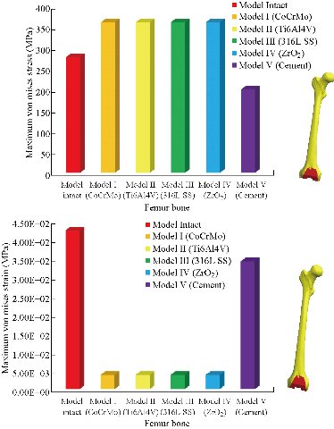
Fig. 14 Histogram of maximum von Mises stresses and strains in the femur bone for different biomaterials.
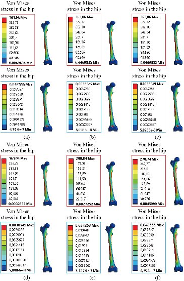
Fig. 15 Distribution of maximum von Mises stresses and strains in the femur bone for different biomaterials: (a) CoCrMo; (b) Ti6Al4V; (c) 316 L SS; (d) ZrO2; (e) Model with cement; and (f) Intact model (knee joint).
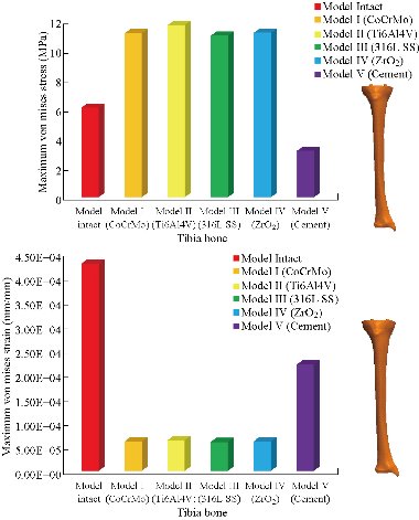
Fig. 16 Histogram of maximum von Mises stresses and strains in the tibia bone between different biomaterials.
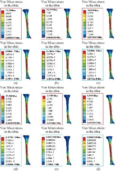
Fig. 17 Distribution of maximum von Mises stresses and strains in the tibia bone between different biomaterials: (a) CoCrMo; (b) Ti6Al4V; (c) 316 L SS; (d) ZrO2, (e) Model with cement; (f) Intact model (knee joint).
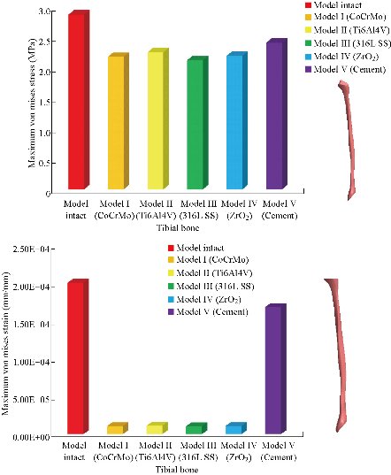
Fig. 18 Histogram of maximum von Mises stresses and strains in the tibial bone between different biomaterials.
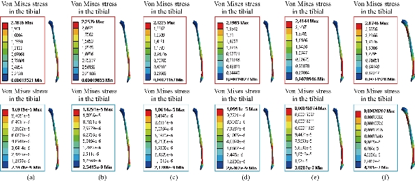
Fig. 19 Distribution of maximum von Mises stresses and strains in the tibial bone between different biomaterials: (a) CoCrMo; (b) Ti6Al4V; (c) 316 L SS; (d) ZrO2; (e) Model with cement; and (f) Intact model (knee joint).

Fig. 20 Histogram of maximum von Mises stresses and strains in the femoral component between different biomaterials.
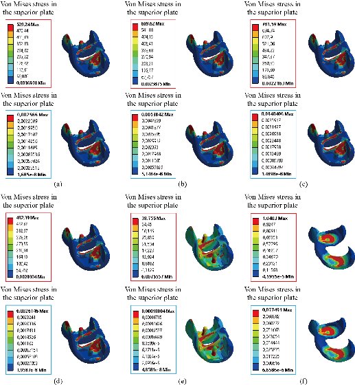
Fig. 21 Distribution of maximum von Mises stresses and strains in the implant superior of the prosthesis of knee between different biomaterials: (a) CoCrMo; (b) Ti6Al4V; (c) 316 L SS; (d) ZrO2; (e) Model with cement; and (f) Cartilage femoral.
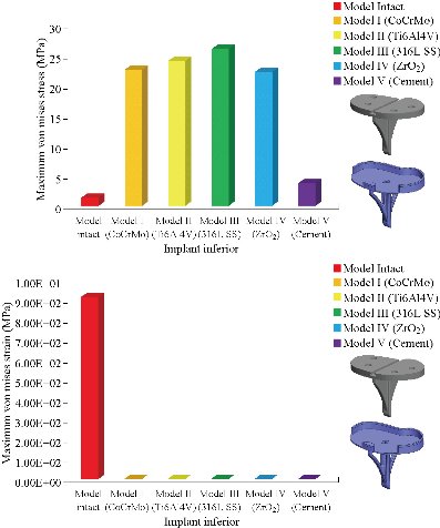
Fig. 22 Histogram of maximum von Mises stresses and strains in the tibial component between different biomaterials.
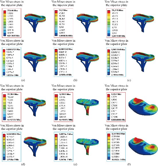
Fig. 23 Distribution of maximum von Mises stresses and strains in the implant inferior of the prosthesis of knee for different biomaterials: (a) CoCrMo; (b) Ti6Al4V; (c) 316 L SS; (d) ZrO2; (e) Model with cement; and (f) Tibial cartilage.
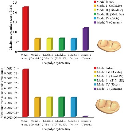
Fig. 24 Histogram of maximum von Mises stresses and strains in the polyethylene tray for different biomaterials.
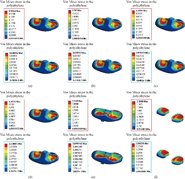
Fig. 25 Distribution of maximum von Mises stresses and strains in the rod polyethylene of the prosthesis of knee between different biomaterials: (a) CoCrMo; (b) Ti6Al4V; (c) 316 L SS; (d) ZrO2; (e) Model with cement; and (f) Menisci.
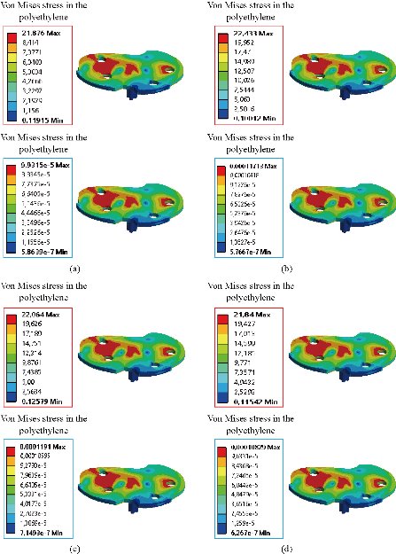
Fig. 26 Distribution of maximum von Mises stresses and strains in the implant medium of the prosthesis of knee for different biomaterials: (a) CoCrMo; (b) Ti6Al4V; (c) 316 L SS; and (d) ZrO2.
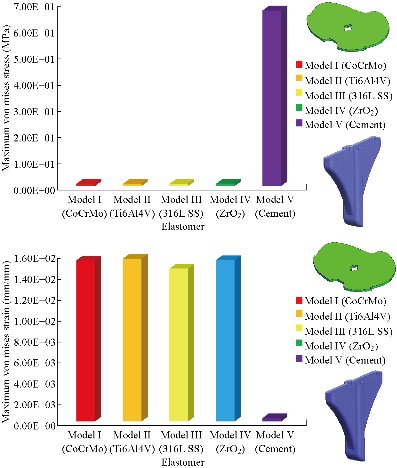
Fig. 27 Histogram of maximum von Mises stresses and strains in the patella bone between different biomaterials.
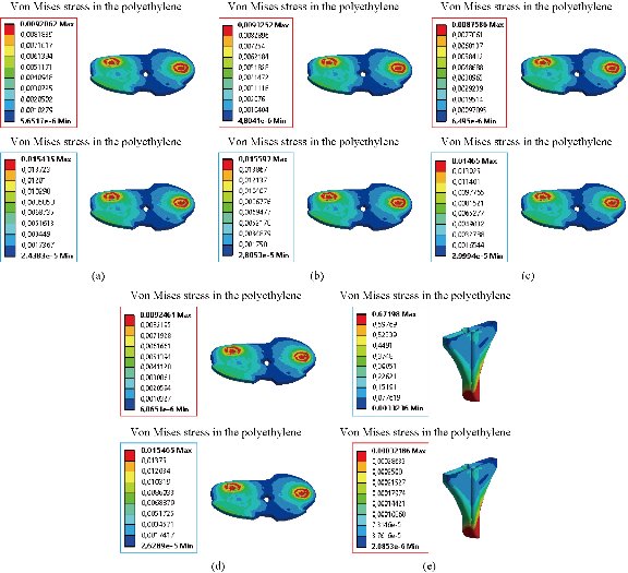
Fig. 28 Distribution of maximum von Mises stresses and strains in the elastomer of the prosthesis of knee between different biomaterials: (a) CoCrMo; (b) Ti6Al4V; (c) 316 L SS; (d) ZrO2; (e) Model with cement; and (f) Intact femur.
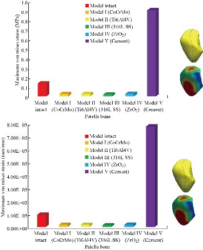
Fig. 29 Histogram of maximum von Mises stresses and strains in the patella bone between different biomaterials.
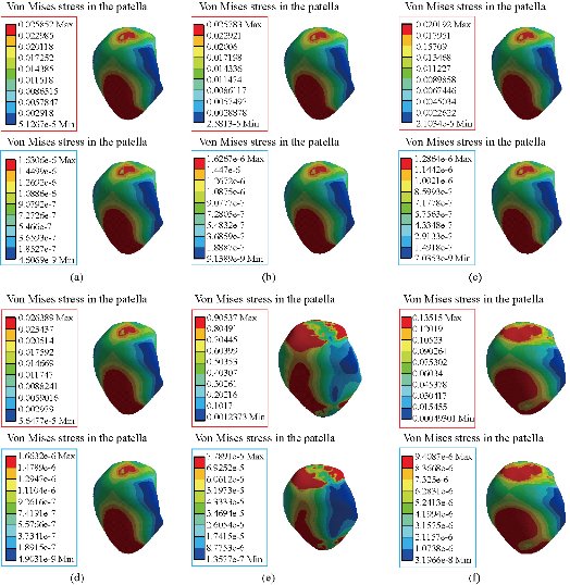
Fig. 30 Distribution of maximum von Mises stresses and strains in the patella of the prosthesis of knee: (a) CoCrMo; (b) Ti6Al4V; (c) 316 L SS; (d) ZrO2; (e) Model with cement; and (f) Intact femur.
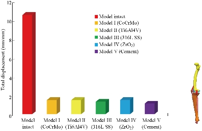
Fig. 31 Histogram of the total displacement of the model biomechanical of knee prosthesis between different biomaterials.
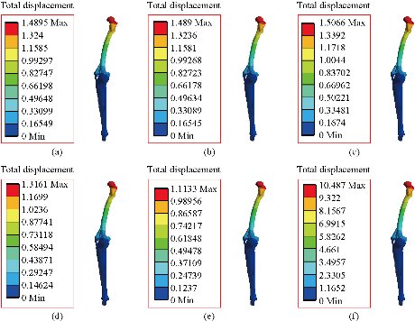
Fig. 32 Distribution of maximum total displacement of the model biomechanical of knee prosthesis: (a) CoCrMo; (b) Ti6Al4V; (c) 316 L SS; (d) ZrO2; (e) Model with cement; and (f) Intact model.
Conclusions
FEA, an effective tool for the analysis of diseases at the knee level, was used to establish a complete 3D nonlinear model (intact model) with the ligaments of solid elements; then it was modified to simulate the two total knee prostheses (model I with elastomer and model V with cement). To compare the three surgical models under physiological load conditions, they were subjected to the axial compression loading P1 that was applied to the upper surface of the femur. It was revealed in this study that the maximum von Mises stresses and strains at the level of tibial and tibial bone decreased, i.e. cement and elastomer played a very important role in the absorption of stresses and their minimization. On the other hand, the four knee prostheses (model I, model II, model III and model IV) implanted by elastomer contributed significantly to the reduction of stresses in the patella bone as compared to the intact model. In general, both models of the knee prosthesis and those reinforced by a stress reduction system (cement or elastomer) gave a lower stress level in the tibia and tibial bone of a normal person as compared to a healthy model. The results obtained provide a theoretical basis for choosing an appropriate surgical model.
Acknowledgements
The author kindly appreciates Mr. Nourddine Zina and Ahmed Boutaousa for their help in model preparation.
Authors’ contributions
All authors had equal role in design, work, statistical analysis and manuscript writing.
Funding / Support
This paper was done by personal expenses.
Conflict of Interests
The authors declare that no competing interest exists.
References
Copyright© Abdelkader Mestar, Samir Zahaf, Nourddine Zina, and Ahmed Boutaous. This is an open-access article distributed under the terms of the Creative Commons Attribution License, which permits unrestricted use, distribution, and reproduction in any medium, provided the original author and source are credited.

|
Nano Biomedicine and Engineering. Copyright © Shanghai Jiao Tong University Press |
 |