Research on Measurement of Nano Magnetic Fluid Viscosity in Variable Magnetic Field
Fei Qiao 1, Kundong Wang 2*, Wencan Gao 2
1 Power China Enqipment Research Institute, Yishan Rd. 900, Shanghai 201306, China.
2 Department of Instrument Engineering, Shanghai Jiao Tong University, 800 Dongchuan Rd., Shanghai 200240, China.
* Corresponding author. E-mail: kdwang@sjtu.edu.cn; Tel.: +86(0)21-34204627; Fax: +86(0)21-34204434.
Received: Dec. 21, 2017; Accepted: Dec. 27, 2017; Published: Dec. 30, 2017
Citation: Fei Qiao, Kundong Wang, and Wencan Gao, High-purified Isolation and Proteomic Analysis of Urinary Exosomes from Healthy Persons. Nano Biomed. Eng., 2017, 9(4): 337-343.
DOI: 10.5101/nbe.v9i4.p337-343.
Abstract
To measure viscosity of magnetic fluids (MFs) in adjustable magnetic field, this paper presented a novel method using a double tube and a torque measuring motor. The inner tube was fixed and the outer tube was driven by a motor. Mathematical analysis indicated that the viscosity of MFs in the gap between the two tubes could be determined by the rotational speed. A magnetic circuit constructed by some permanent magnets and yokes provided the magnetic field for the MFs in the gap. Changing the number of the magnets could adjust the magnetic density easily. Taking the temperature’s influence on the viscosity into account, an extrapolation method was adopted to measure and control the MFs’ temperature precisely. This method was calibrated by the standard liquid with the known viscosity, which showed that the mean error was less than 0.82%. This method was used to measure the viscosity of MFs composed of MnZnFeO4 nanoparticles, oleic acid surfactants and lubricant carrier liquid in variable magnetic field at the different temperatures.
PACS: 75.30.Gw; 75.50.Tt; 75.60.Lr
Keywords: Magnetic fluids; Viscosity; Variable magnetic field; Dynamical sealing
Introduction
As a new type of liquid functional material, magnetic fluids (MFs) can be widely used in many fields such as mechanical sealing and lubricating, biomedicine and sensors [1-4]. In these fields, the sealing holds the hot attention of many researchers. At present, the vacuum and gas sealing used MFs have been applied successfully in industry. But there are few reports on liquid dynamic sealing because the stability question of interface between MFs and sealed liquid is not solved well. Researchers try to solve it through two strategies. The first is to synthesize the MFs not dissolved in sealed medium [5]. The second is to study the influence of magnetic field on interface stability for designing reasonable sealing mechanism [6]. MFs have different viscosity in different magnetic field, which is significant to interface stability [7, 8]. Measuring the MFs’ viscosity in the variable magnetic field and studying its change law are the keys to solving problems in MFs liquid dynamic sealing. There have been some reports on measuring MFs’ viscosity. Mctague firstly used a capillary viscometer to measure the viscosity of toluene-based cobalt magnetic fluid in the magnetic field [9]. He found that MFs had different viscosity while changing direction of magnetic field. Viscosity in the magnetic field parallel with flow shearing surface was twice as one in the field vertical with shearing surface. However, when the field became stronger, the MFs’ concentration was changed to be so large that the MFs could not flow. Therefore, this method is not feasible. Deysakar et al. developed a digital Brook-field viscometer with a non-magnetic axle and a permanent placed beside a MFs sample room [10]. Steiner developed a dynamic viscometer to the magnetic fluids [11]. Magnetic field is changed by changing distance between the magnet and the sample. Obviously, its result is qualitative because of the field’s fast attenuation with regard to the distance. In This paper, a new type of viscometer to measure viscosity of magnetic fluids in different magnetic fields at different temperatures is developed. Variable magnetic field is applied on magnetic fluids through magnetic circuit simulating the working condition of liquid dynamic sealing. Double concentric barrels are used in system. The outer barrel is fixed and the inner barrel is drove by a motor. The interval of the outer barrel and inner barrel is filled with MFs. Theoretically, mathematical relation equation between rotational speed of the motor and MFs’ viscosity is reduced. MFs’ temperature is measured precisely based on the extrapolation method. At last, viscometer is calibrated with standard liquid.
Structure of the Measurement System
There are many test methods for measuring ordinary liquid’s viscosity, such as the flowing-out method, the revolving method, the falling-body method and so on. Because the viscosity of MFs is affected greatly by magnetic field applied in test and MFs mostly is of deep color, it is improper to adopt falling-body method and flowing-out method. Here, revolving method is used in this paper. Principle of this method is very simple. When axial symmetry body such as cylinder or disk revolves in liquid, the shearing force of liquid will form shearing resistance torque on the surface of the body. This resistance torque is related to MFs’ viscosity. We can obtain the liquid’s viscosity through measuring torque. Simplified 3D schematic of the viscometer is shown in Fig. 1. There are two concentric tubes in system. The outer is fixed and the inner is drove by motor. The MFs are filled in the interval between the outer barrel and the inner barrel. There is a certain mathematic relation between the viscosity and the rotation speed of motor. Magnetic circuit is closed passing though the permanent, yoke and MFs. Changing number of permanents settled in the outer barrel is used to adjust the magnetic field applied on MFs. The whole system is placed into a thermostat water bath with high precision. Electric thermal couples settled in holes with average increasing depth are used to precisely test actual temperature in MFs.
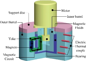
Fig. 1 Simplified 3D schematic of viscometer for magnetic fluids.
Measurement System Design
Working characteristic equation
While working, the outer barrel is fixed, and MFs to be measured will fill the interval between inner barrel and outer barrel. The MFs revolve because of the inner barrel’s rotation. Because the internal is very narrow and the inner barrel revolves with uniform velocity, the flow of MFs can be regarded as Couette flow. We have:
![]() , (1)
, (1)
where Mz is the inner barrel’s resistance torque (N·m), r1 is the inner barrel’s radius (m), r2 is the outer barrel’s radius (m), n is the inner barrel’s rotational speed (rad/s), L is the inner barrel’s length (m), and η is dynamic viscosity of the MFs (g/mm·s). From equation (1), η can be obtained by measuring Mz and n if structural parameters of the inner barrel and the outer barrel are known. In fact, the test instrumental can not be allocated exactly to inner barrel. Additionally, external magnetic field’s influence on test instrument can not be eliminated absolutely even if torque measuring instrument with high accuracy is used. So Measuring Mz precisely becomes very difficult. Here, we focus on n’ variation related to the change of Mz. this idea not only meets measuring demand but also avoids above difficulties. Because of the rigid connection between the inner barrel and shaft of motor, the rotational speed of motor is also equal to n. If a resistance R is in series with DC motor circuit, the motor’s man-made mechanical characteristic can be written as
![]() , (2)
, (2)
where RBa is the total resistance of motor armature (Ω), UN is the electric center’s fixed voltage (V), Ce is the voltage constant, CT is the turn-torque constant, T is the torque (N•m), and ΦN is the normal magnetic flux for each pole in the air gap (Wb). If the motor’s parameters and the resistance in series are constant, n is the linear function of T. That is
![]() , (3)
, (3)
where nB0 is the empty-loaded rotational speed (turn/s), and β is man-made machine specific slope which can be written as ![]() , where Ra is the resistance of the armature (Ω), R is the resistance in series (Ω). Obviously, when R is very large, its sensitivity is very high as shown in Fig. 2. T can be obtained through measuring n. When the motor rotates at uniform speed, Mz=-T. Substituting equation (1) into equation (2) gives
, where Ra is the resistance of the armature (Ω), R is the resistance in series (Ω). Obviously, when R is very large, its sensitivity is very high as shown in Fig. 2. T can be obtained through measuring n. When the motor rotates at uniform speed, Mz=-T. Substituting equation (1) into equation (2) gives
![]() .
.
Assume
![]() . Thus,
. Thus, ![]() .
.
Let A be a/b and B be 1/b, then above equation can be simplified as
![]() , (4)
, (4)
where A and B are constant coefficients about structural dimension. Equation (4) is the working characteristic equation of measuring system for MFs’ viscosity.
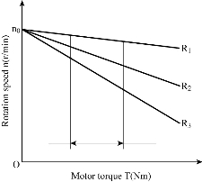
Fig. 2 Mechanical character of DC motor.
Magnetic circuit’s structural design
With regard to the aim of this measurement system, magnetic field direction is designed to be vertical to flowing shearing surface as shown in Fig. 1. This simulates the working condition of the MFs’ liquid dynamic sealing. Working magnetic circuit is composed of permanent magnet, yoke with high magneto-conduct and working air gap filled with MFs. Magnetic field is provided with permanent magnet. Because the interval is very thin so magnetic field applied on the MFs can be thought of as uniform. Permanent magnets are settled uniformly in circumferential direction of the outer barrel. Through changing numbers of permanent magnets, the magnetic field in working gap can be changed between 0~H.
Precise measuring of temperature
MFs’ viscosity varies greatly with the change of its temperature, so MFs’ temperature must be accurately measured. To keep the temperature constant throughout the test, the system is put into a thermostat water bath with high precision. Because the shearing motion of MFs in gap produces heat, measured MFs’ temperature is higher than one of water bath. The temperature of water bath is still stable when a part of heat is transferred to it, because water bath is very large in contrast with measured MFs. However, there is a difference between measured liquid’s temperature and water bath temperature because of the retard of heat transferring. So we can not take the temperature of water bath as the temperature of MFs. In order to test the actual temperature of the MFs, the temperature must be accurately measured before the beginning of shearing motion. Thermo electric couples are used in the test. The thermocouples can’t directly touch liquid, so measured temperature has large error. An extrapolation method is used as shown in Fig. 1. Some holes with difference depth are drilled at outer barrel. Thermocouples can measure the temperatures at different distance from MFs. The actual temperature of MFs can be obtained by extrapolation.
Inner and outer barrel dimension
While calibrating the instrumental coefficient, standard liquid is used to assure the flowing to be laminar flow, which meets the equation:
RBeR < RecR = 500, (5)
where RBeR is Reynolds number for non-round pipe flow, and RBecR is critical Reynolds number for non- round pipe laminar flow. Non-round flow Reynolds number can be written as
![]() , (6)
, (6)
where V is the rotational speed (V=rB1Bn/60), and R is the hydraulic radius (m, R=A/Χ). Substituting the flow section area A=(rB2B-rB1B)L and the wetted perimeter Χ=2L into formula (6) gives:
![]() . (7)
. (7)
Taking it into equation (5) gives
![]() . (8)
. (8)
Taking factors such as machining and assembly etc. into account, we can take r1-r2=0.5mm. If liquid with low viscosity is laminar flow, liquid with high viscosity must also be laminar flow. So v=1.0 mmP2P/s. Let n be motor’s empty-loaded rotational speed n0=700r/min, and then taking these values into equation (8) gives r1< 27.3 mm. Motor’s rotational speed must be lower in loaded status than one in empty-loaded case. Let r1=20.0mm, r2=20.5mm, and taking them into equation (7) gives RBeR =366.5 <500. Obviously, it can meet the measure demand according to equation (5).
Motor and device for measuring rotational speed
Beijing micro motor factory’s permanent magnetic D.C. motor with model SYL–2.5 is used in the system. Motor’s main technical parameters include peak block-up torque 0.245 N•m, peak block-up current 1.6 A, peak block-up voltage 20 V, and empty load rotational speed 700 r/min. Hioki 3402-module speed measuring meter is used to measure D.C. motor’s rotational speed. When the motor is running at uniform speed, MZ =-T. Let the driving force torque be peak block-up force torque, then T=0.245Nm. Let inner barrel length L=85mm, then measured liquid’s viscosity η=20N•s /mP2. Taking these values into equation (1) gives N=13.2r/min > 0. Obviously it can meet the driving demand. According to the test principle, increasing motor armature resistance can raise system’s sensitivity, so the resistance should be as large as possible. While sensitivity’s improvement leads to decreasing of the motor’s load, resistance can not be very large. It must have a threshold. Let the working temperature be at 20 ℃ and let the working voltage be 20 V, No.7 standard liquid with high viscosity is used. Different resistance is in series with the motor armature, motor’s rotating speed is shown in Table 1. So, R<20Ω.
Table 1 Rotational speed of motor with different resistance in series
|
Resistance ( |
0 |
5 |
10 |
20 |
|
Rotate speed(r/min) |
42.63 |
31.11 |
25.35 |
stop |
Calibration of Measuring System
Calibration of thermocouple
MFs’ working temperature usually varies from 20 ℃ to 60 ℃, so the calibrated temperature of thermocouple is between 15 ℃ and 70 ℃. Standard Pt-Rh 10-Pt thermocouple is used to calibrate the thermocouple. The result is shown in Fig. 3. Least square method is used to make linear regression. Thermocouple’s working characteristic equation can be written as
![]() ,
,
where E is the thermo electromotive force (mV), and t is the temperature (oC). The Measured result is analyzed for interrelation. Correlation efficient R = 0.9998 is obtained. Obviously, there’s a good linear correlation between E and t.
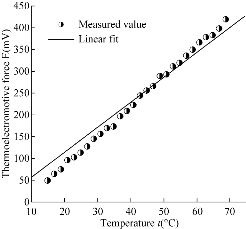
Fig. 3 Characteristic curve of the thermocouple.
Calibration of working characteristic equation
Standard liquid is used to calibrate the system’s working characteristic equation. The temperature is 20 ℃, 40 ℃ and 50 ℃ respectively. The resistance in series with armature is 10 Ω, 5 Ω and 0 Ω respectively. Calibration results are shown in Fig. 4. Least square method is used to process experimental data in linear regression and interrelation analysis. Results are shown in Table 2. According to Table 2, the lager the resistance in series with armature is, the stronger the linear correlation of viscosity η with 1/n is. To judge the effectiveness of the regression, standard liquids with different viscosity at 20 ℃ are tested. The result is compared with actual viscosity of the liquid at the same temperature. The relative errors are shown in Table 3. From Table 3, the relative error is small and tolerable. When resistance in series is 10 Ω, relative error is the least one, which is consistent with the result of correlation analysis. So resistance of 10 Ω should be in series with armature.
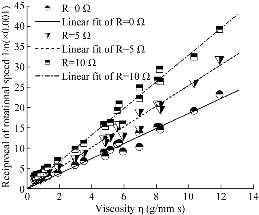
Fig. 4 Calibration result of the MFs viscosity.
Table 2 Relative error of standard liquids with different viscosity
|
Resistance (Ω) |
System coefficients (A0,B0) |
Correlation coefficients between η and 1/n |
|
0 |
A0=560.379, B0=0.340 |
0.9889 |
|
5 |
A0=400.815, B0=0.183 |
0.9914 |
|
10 |
A0=311.506, B0=0.213 |
0.9933 |
Table 3 Relative error of measurement of standard liquid with different viscosity
|
Standard liquid tab |
Real viscosity η20 (g/mm·s) |
Resistance (Ω) |
Measurement η20 (g/mm·s) |
Relative error (%) |
|
6 |
1.975 |
0 |
1.926 |
2.48 |
|
5 |
2.011 |
1.82 |
||
|
10 |
1.977 |
0.11 |
||
|
7 |
8.121 |
0 |
8.254 |
1.64 |
|
5 |
8.290 |
2.08 |
||
|
10 |
8.172 |
0.63 |
||
|
8 |
11.977 |
0 |
12.806 |
6.92 |
|
5 |
12.700 |
6.04 |
||
|
10 |
12.075 |
0.82 |
Calibration of barrel-bottom effect
MFs will fill the bottom as shown in Fig. 1. While deriving equation (1), only resistance torque of liquid in the side interval, not including with one at bottom, is considered. Influence of this resistance torque produced by bottom on measurement is called as the barrel-bottom effect. To improve measuring accuracy, effect of barrel bottom must be considered. It can be revised by equivalent of MFs height in interval. It is considered that resistance torque produced by effect of barrel bottom is equal to resistance torque produced by ΔL which is defined as the virtual increasing of interval MFs height. ΔL is only determined by the distance between the inner and outer barrel bottom. When structural parameters are determined, ΔL must be a constant coefficient. After revision, characteristic equation can be expressed as
![]() . (9)
. (9)
Standard measured liquid with known viscosity is poured into interval. Height of liquid is adjusted to L1 and L2, which is corresponding to motor rotational speed n1 and n2 respectively. Then taking these values into equation (9) gives:
![]() and
and ![]() .
.
Eliminating η from the above two equations gives:
![]() .
.
Here standard liquids with various viscosities are used. n1 and n2 are tested when L1=85 mm (completely immerging) and L2=47.5 mm (half immerging) respectively. From the above equation, Table 4 is obtained. Finally three revision’s average ΔL=13.62 mm is taken.
Table 4 Calibration of bottom effect at the 20 ℃
|
Standard liquid tab |
Viscosity η20 (g/mm·s) |
Rotate speed of motor (r/min) |
L (mm) |
|
|
L1=85.0 mm |
L2=47.5 mm |
|||
|
6 |
1.975 |
140.97 |
215.22 |
13.22 |
|
7 |
8.121 |
37.15 |
58.90 |
13.97 |
|
8 |
11.977 |
25.35 |
40.46 |
13.67 |
Measurement of Viscosity
The developed viscometer is used to measure the viscosity of the magnetic fluid at different temperature in the variable magnetic field. The magnetic fluid is prepared by dispersing the nano-magnetic particle ferrite coated with the oleic acid in the coal oil. Three groups of experiments are designed to explore the viscosity of the magnetic fluids. The magnetic field applied in the magnetic fluids is adjusted by altering the number of the embodied permanent-magnets. Although the quantitative magnetic field can not be defined, some change laws tendency will be determined by this method. The first group is used to measure the viscosity of the magnetic fluid with the different mass percent density at room temperature.
Conclusions
This measuring system consists of revolving inner barrel and fixed outer barrel. Measured liquid is filled in the interval between the inner barrel and the outer one. Viscosity is DC motor rotational speed’s function according to its work characteristic equation. Magnetic field applied on MFs is vertical to flowing shearing direction, which simulates the working condition of dynamic sealing. Measuring method by extrapolation can accurately measure MFs’ temperature. The system is calibrated with standard liquid, and the calibration result shows that the system’s relative error is very small. When the resistance of 10 Ω is in series, the relative error is smaller than 0.82%. So it can meet the measurement’s demand very well. This viscometer is expected to be applied in the research on interface stability of dynamic liquid sealing in the future.
Acknowledgements
The authors should thank Ms. Jiang and Dr. Ye for their jobs in the development of the system. This research is supported by the research grants from Shanghai Engineering Research Center for Intelligent Diagnosis and Treatment Instrument (15DZ2252000).
Conflict of Interests
The authors declare that no competing interest exists.
References
Copyright© Fei Qiao, Kundong Wang, and Wencan Gao. This is an open-access article distributed under the terms of the Creative Commons Attribution License, which permits unrestricted use, distribution, and reproduction in any medium, provided the original author and source are credited.

|
Nano Biomedicine and Engineering. Copyright © Shanghai Jiao Tong University Press |
 |